
NCE-Guiguo SiC IPM: Silicon Carbide Intelligent Power Modules Redefine Efficiency
Time: 2026-07-30 14:09:24
For decades, silicon-based intelligent power modules (IPMs) have been the workhorse of motor drives, inverter stages, and power conversion. But as efficiency mandates tighten and power density expectations climb, silicon is approaching its physical limits. The answer that the industry has been waiting for is now a production reality: silicon carbide (SiC) IPMs. And in mid-2026, Wuxi NCE Power Co., Ltd. and National Silicon (Guiguo) jointly launched a comprehensive SiC IPM portfolio that brings wide-bandgap performance into the same industry-standard footprints as legacy silicon IPMs — with PIN-to-PIN compatibility.
 Figure 1: NCE-Guiguo SiC IPM — 600V/7A–15A, five packages, PIN-to-PIN silicon IPM replacement.Silicon Has Hit the Wall — SiC IPM Is the Next Chapter in Power Electronics
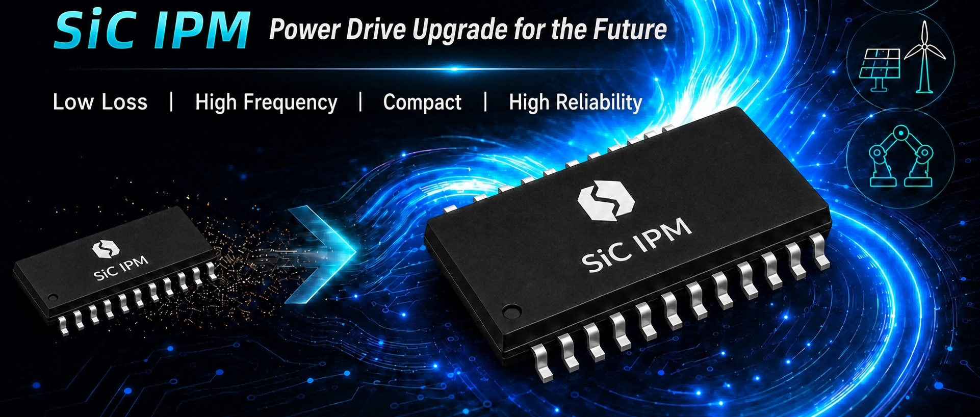
Figure 1: NCE-Guiguo SiC IPM — 600V/7A–15A, five packages, PIN-to-PIN silicon IPM replacement.
The newly released series covers 600V / 7A–15A across five mainstream package types — PQFN5×6, SOP16W, SOP23, DIP23, and ESOP13 — integrating a SiC MOSFET power stage with a high-voltage gate driver, bootstrap diodes, undervoltage protection, and temperature sensing all within a single package. The result: a drop-in upgrade that cuts switching losses by over 70%, reduces conduction losses by over 50%, and boosts end-system efficiency by 1–3 percentage points — while potentially shrinking the inverter footprint by up to 50%.
Five Performance Leaps That Redefine Your Power Stage
Switching from a conventional silicon IGBT-based IPM to an NCE-Guiguo SiC IPM is not an incremental change — it is a step-function improvement across every metric that matters for modern power electronics design:
| Performance Metric | Si IGBT IPM (Typical) | NCE-Guiguo SiC IPM | Improvement |
|---|---|---|---|
| Switching Loss | Baseline | SiC MOSFET with near-zero reverse recovery | −70%+ |
| Conduction Loss | VCE(sat) ~1.5–2.0V at rated current | SiC Rds(on) in single-digit mΩ range | −50%+ |
| System Efficiency | ~93–96% typical inverter stage | Gains from reduced conduction + switching losses | +1 to 3 percentage points |
| Inverter Footprint | Heatsink-dominated layout | Lower losses → smaller heatsink → compact PCB | −30% to 50% potential |
| Junction Temperature Capability | 150°C (silicon limit) | SiC wide-bandgap intrinsic capability | 175°C+ |
These five leaps compound: lower losses mean less heat, which means smaller or even fanless thermal solutions, which means more compact end products. Higher junction temperature capability opens up deployment in environments — engine compartments, rooftop solar inverters, unventilated industrial cabinets — where silicon IPMs require aggressive derating or active cooling.
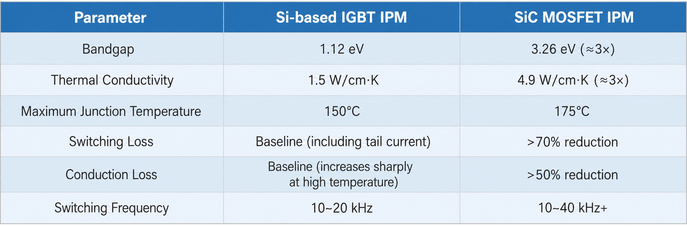
Figure 2: SiC IPM vs silicon IGBT IPM — 70%+ lower switching loss, 50%+ lower conduction loss.
Inside the Module: What Makes SiC IPM Integration a Game-Changer
1. SiC MOSFET Power Stage — The Core Differentiator
Unlike silicon IGBTs that suffer from tail current during turn-off, the SiC MOSFET is a majority-carrier device with near-instantaneous switching. This eliminates the dominant switching-loss mechanism in hard-switched inverter stages. Combined with the absence of reverse-recovery charge from the SiC body diode, both turn-on and turn-off losses collapse — enabling higher PWM frequencies without the typical efficiency penalty.
2. Monolithically Integrated High-Voltage Gate Driver
The on-chip gate driver is designed specifically for SiC MOSFET gate-drive requirements — including the higher gate-source threshold voltage, the need for negative bias during off-state to prevent parasitic turn-on, and the faster dV/dt slew rates that SiC enables. This is not a re-purposed silicon-IGBT driver; it is a SiC-native design.
3. Integrated Bootstrap Diodes & Protection Suite
Each module includes bootstrap diodes for the high-side floating supply, undervoltage lockout (UVLO) on both high-side and low-side drivers, and an on-chip temperature sensor. These features reduce external component count by 8–12 passives and simplify PCB layout — directly shortening design cycles by an estimated 30% or more compared to discrete SiC MOSFET + driver implementations.
4. Industry-Standard Footprints for Seamless Migration
The five package options map directly to the most widely used silicon IPM form factors. PQFN5×6 serves ultra-compact designs (power tools, compact drives); SOP16W and SOP23 address mid-power appliances; DIP23 and ESOP13 cover higher-power industrial applications. In most cases, migrating from a same-package silicon IPM requires no PCB layout changes — just drop in the SiC version, adjust the gate-drive resistor values, and realize immediate efficiency gains.
Figure 5: SiC IPM internal block diagram — SiC MOSFET, gate driver, bootstrap, UVLO, temperature sensor.Package Selection Guide: Match Your Application in 30 Seconds
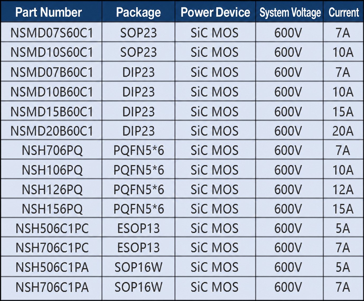
Figure 5: SiC IPM internal block diagram — SiC MOSFET, gate driver, bootstrap, UVLO, temperature sensor.
| Package | Current Rating | Best For | Key Trade-Off |
|---|---|---|---|
| PQFN5×6 | 7A | Power tools, compact motor drives, battery-powered equipment | Smallest footprint; most thermally constrained — best for<200W |
| SOP16W | 10A | Washing machines, refrigerator compressors, small pumps | Good balance of compactness and thermal performance |
| SOP23 | 15A | Air-conditioner fans, mid-range industrial drives | Higher current in a similar SOP footprint |
| DIP23 | 15A | Industrial VFDs, servo drives, high-temp environments | Through-hole robustness; excellent thermal dissipation |
| ESOP13 | 15A | Solar microinverters, energy-storage PCS, high-speed spindles | Exposed pad for enhanced heat-sinking; 30–50% system size reduction achievable |
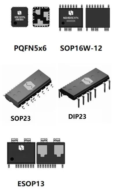
Figure 3: NCE-Guiguo SiC IPM — 600V/7A–15A, PQFN5×6, SOP16W, SOP23, DIP23, ESOP13.
Application Map: Where SiC IPM Delivers the Highest Return
| Application Domain | Why SiC IPM Wins | Quantified Benefit |
|---|---|---|
| Industrial VFDs & Servo Drives | Higher PWM frequency → smoother sinusoidal current → lower motor harmonic losses and audible noise | 1–2% motor system efficiency gain; reduced or eliminated output filter |
| Solar Inverters & Energy Storage PCS | Lower conduction + switching losses directly improve MPPT-to-grid round-trip efficiency | 1–3% efficiency gain → measurably higher annual energy yield per installed kW |
| Inverter Home Appliances | Smaller heatsink → slimmer product profile; higher efficiency → lower energy bills for end users | 30–50% inverter PCB area reduction; improved energy-label rating |
| Power Tools & High-Speed Motors | SiC's high-frequency capability enables compact, lightweight motor control in battery packs | Longer runtime per charge; smaller, lighter tool design |
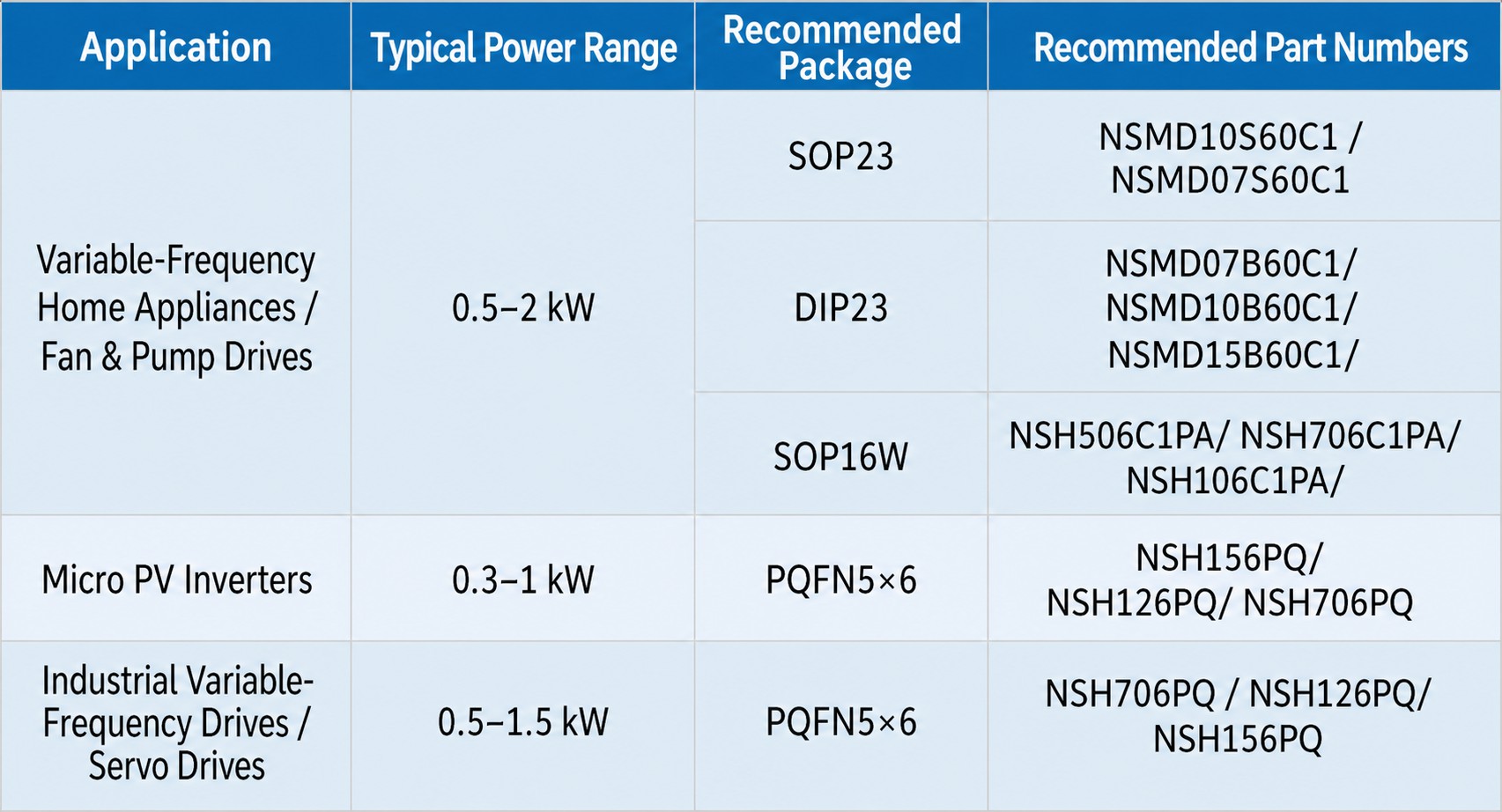
Figure 4: SiC IPM target applications — industrial drives, solar inverters, home appliances, power tools.
FAQ: Your SiC IPM Transition Questions, Answered
Q: Is it really a drop-in replacement, or are there hidden design changes required?
A: The modules are mechanically and footprint-compatible with their silicon IPM counterparts in the same package type. The primary design adjustments are: (1) gate-drive resistor values may need tuning for SiC's faster switching characteristics, and (2) if you choose to exploit the higher PWM frequency capability, the microcontroller's timer configuration changes. Neither requires PCB re-spin. The power-stage layout, current-sensing resistors, and DC-link capacitor positions remain unchanged.
Q: What about cost? SiC has historically carried a premium over silicon.
A: The per-unit cost of a SiC IPM is higher than an equivalent silicon IPM — this is the current reality of wide-bandgap technology. However, the system-level cost often favors SiC: smaller heatsink (or fan removal), reduced or eliminated output filter, smaller enclosure, and lower assembly cost. For energy-sensitive applications (solar, appliances), the efficiency gain alone can justify the BOM delta within 12–18 months of operation. We recommend a system-level cost analysis rather than a component-level comparison.
Q: What design support can YQM provide during the evaluation phase?
A: We supply evaluation boards, reference designs, datasheets, and application notes for the full NCE-Guiguo SiC IPM portfolio. Our FAE team can review your existing silicon IPM design and provide a migration assessment — identifying the specific resistor value changes, thermal analysis delta, and expected efficiency gain before you commit to prototyping.
Request NCE-Guiguo SiC IPM Evaluation Kit & Migration Assessment
●5 Package Options In Stock
●Free Si-to-SiC Migration Review
●Evaluation Boards Available
●System-Level Cost Analysis
NCE-Guiguo SiC IPM: Silicon Carbide Intelligent Power Modules Redefine Efficiency
Time: 2026-07-30 14:09:24
For decades, silicon-based intelligent power modules (IPMs) have been the workhorse of motor drives, inverter stages, and power conversion. But as efficiency mandates tighten and power density expectations climb, silicon is approaching its physical limits. The answer that the industry has been waiting for is now a production reality: silicon carbide (SiC) IPMs. And in mid-2026, Wuxi NCE Power Co., Ltd. and National Silicon (Guiguo) jointly launched a comprehensive SiC IPM portfolio that brings wide-bandgap performance into the same industry-standard footprints as legacy silicon IPMs — with PIN-to-PIN compatibility.
Figure 1: NCE-Guiguo SiC IPM — 600V/7A–15A, five packages, PIN-to-PIN silicon IPM replacement.Silicon Has Hit the Wall — SiC IPM Is the Next Chapter in Power Electronics
Figure 1: NCE-Guiguo SiC IPM — 600V/7A–15A, five packages, PIN-to-PIN silicon IPM replacement.
The newly released series covers 600V / 7A–15A across five mainstream package types — PQFN5×6, SOP16W, SOP23, DIP23, and ESOP13 — integrating a SiC MOSFET power stage with a high-voltage gate driver, bootstrap diodes, undervoltage protection, and temperature sensing all within a single package. The result: a drop-in upgrade that cuts switching losses by over 70%, reduces conduction losses by over 50%, and boosts end-system efficiency by 1–3 percentage points — while potentially shrinking the inverter footprint by up to 50%.
Five Performance Leaps That Redefine Your Power Stage
Switching from a conventional silicon IGBT-based IPM to an NCE-Guiguo SiC IPM is not an incremental change — it is a step-function improvement across every metric that matters for modern power electronics design:
| Performance Metric | Si IGBT IPM (Typical) | NCE-Guiguo SiC IPM | Improvement |
|---|---|---|---|
| Switching Loss | Baseline | SiC MOSFET with near-zero reverse recovery | −70%+ |
| Conduction Loss | VCE(sat) ~1.5–2.0V at rated current | SiC Rds(on) in single-digit mΩ range | −50%+ |
| System Efficiency | ~93–96% typical inverter stage | Gains from reduced conduction + switching losses | +1 to 3 percentage points |
| Inverter Footprint | Heatsink-dominated layout | Lower losses → smaller heatsink → compact PCB | −30% to 50% potential |
| Junction Temperature Capability | 150°C (silicon limit) | SiC wide-bandgap intrinsic capability | 175°C+ |
These five leaps compound: lower losses mean less heat, which means smaller or even fanless thermal solutions, which means more compact end products. Higher junction temperature capability opens up deployment in environments — engine compartments, rooftop solar inverters, unventilated industrial cabinets — where silicon IPMs require aggressive derating or active cooling.
Figure 2: SiC IPM vs silicon IGBT IPM — 70%+ lower switching loss, 50%+ lower conduction loss.
Inside the Module: What Makes SiC IPM Integration a Game-Changer
1. SiC MOSFET Power Stage — The Core Differentiator
Unlike silicon IGBTs that suffer from tail current during turn-off, the SiC MOSFET is a majority-carrier device with near-instantaneous switching. This eliminates the dominant switching-loss mechanism in hard-switched inverter stages. Combined with the absence of reverse-recovery charge from the SiC body diode, both turn-on and turn-off losses collapse — enabling higher PWM frequencies without the typical efficiency penalty.
2. Monolithically Integrated High-Voltage Gate Driver
The on-chip gate driver is designed specifically for SiC MOSFET gate-drive requirements — including the higher gate-source threshold voltage, the need for negative bias during off-state to prevent parasitic turn-on, and the faster dV/dt slew rates that SiC enables. This is not a re-purposed silicon-IGBT driver; it is a SiC-native design.
3. Integrated Bootstrap Diodes & Protection Suite
Each module includes bootstrap diodes for the high-side floating supply, undervoltage lockout (UVLO) on both high-side and low-side drivers, and an on-chip temperature sensor. These features reduce external component count by 8–12 passives and simplify PCB layout — directly shortening design cycles by an estimated 30% or more compared to discrete SiC MOSFET + driver implementations.
4. Industry-Standard Footprints for Seamless Migration
The five package options map directly to the most widely used silicon IPM form factors. PQFN5×6 serves ultra-compact designs (power tools, compact drives); SOP16W and SOP23 address mid-power appliances; DIP23 and ESOP13 cover higher-power industrial applications. In most cases, migrating from a same-package silicon IPM requires no PCB layout changes — just drop in the SiC version, adjust the gate-drive resistor values, and realize immediate efficiency gains.
Figure 5: SiC IPM internal block diagram — SiC MOSFET, gate driver, bootstrap, UVLO, temperature sensor.Package Selection Guide: Match Your Application in 30 Seconds
Figure 5: SiC IPM internal block diagram — SiC MOSFET, gate driver, bootstrap, UVLO, temperature sensor.
| Package | Current Rating | Best For | Key Trade-Off |
|---|---|---|---|
| PQFN5×6 | 7A | Power tools, compact motor drives, battery-powered equipment | Smallest footprint; most thermally constrained — best for<200W |
| SOP16W | 10A | Washing machines, refrigerator compressors, small pumps | Good balance of compactness and thermal performance |
| SOP23 | 15A | Air-conditioner fans, mid-range industrial drives | Higher current in a similar SOP footprint |
| DIP23 | 15A | Industrial VFDs, servo drives, high-temp environments | Through-hole robustness; excellent thermal dissipation |
| ESOP13 | 15A | Solar microinverters, energy-storage PCS, high-speed spindles | Exposed pad for enhanced heat-sinking; 30–50% system size reduction achievable |
Figure 3: NCE-Guiguo SiC IPM — 600V/7A–15A, PQFN5×6, SOP16W, SOP23, DIP23, ESOP13.
Application Map: Where SiC IPM Delivers the Highest Return
| Application Domain | Why SiC IPM Wins | Quantified Benefit |
|---|---|---|
| Industrial VFDs & Servo Drives | Higher PWM frequency → smoother sinusoidal current → lower motor harmonic losses and audible noise | 1–2% motor system efficiency gain; reduced or eliminated output filter |
| Solar Inverters & Energy Storage PCS | Lower conduction + switching losses directly improve MPPT-to-grid round-trip efficiency | 1–3% efficiency gain → measurably higher annual energy yield per installed kW |
| Inverter Home Appliances | Smaller heatsink → slimmer product profile; higher efficiency → lower energy bills for end users | 30–50% inverter PCB area reduction; improved energy-label rating |
| Power Tools & High-Speed Motors | SiC's high-frequency capability enables compact, lightweight motor control in battery packs | Longer runtime per charge; smaller, lighter tool design |
Figure 4: SiC IPM target applications — industrial drives, solar inverters, home appliances, power tools.
FAQ: Your SiC IPM Transition Questions, Answered
Q: Is it really a drop-in replacement, or are there hidden design changes required?
A: The modules are mechanically and footprint-compatible with their silicon IPM counterparts in the same package type. The primary design adjustments are: (1) gate-drive resistor values may need tuning for SiC's faster switching characteristics, and (2) if you choose to exploit the higher PWM frequency capability, the microcontroller's timer configuration changes. Neither requires PCB re-spin. The power-stage layout, current-sensing resistors, and DC-link capacitor positions remain unchanged.
Q: What about cost? SiC has historically carried a premium over silicon.
A: The per-unit cost of a SiC IPM is higher than an equivalent silicon IPM — this is the current reality of wide-bandgap technology. However, the system-level cost often favors SiC: smaller heatsink (or fan removal), reduced or eliminated output filter, smaller enclosure, and lower assembly cost. For energy-sensitive applications (solar, appliances), the efficiency gain alone can justify the BOM delta within 12–18 months of operation. We recommend a system-level cost analysis rather than a component-level comparison.
Q: What design support can YQM provide during the evaluation phase?
A: We supply evaluation boards, reference designs, datasheets, and application notes for the full NCE-Guiguo SiC IPM portfolio. Our FAE team can review your existing silicon IPM design and provide a migration assessment — identifying the specific resistor value changes, thermal analysis delta, and expected efficiency gain before you commit to prototyping.
Request NCE-Guiguo SiC IPM Evaluation Kit & Migration Assessment
●5 Package Options In Stock
●Free Si-to-SiC Migration Review
●Evaluation Boards Available
●System-Level Cost Analysis
Other Articles
-
Role of 32.768 kHz in Circuit Design
-
SiTime Automotive Oscillators
-
The Role of 32.768kHz in Circuits
-
Epson RTC modules solve three major pain points of ioT
-
11.0592MHz Crystal Oscillator: The "Heart" of the Computer Motherboard?
-
Examine the cost and design considerations of crystals and oscillators
-
Exploring how YXC oscillators show their skills to help with AI servers
-
Lessons from the Middle East Events — The Importance of Localization!
-
Good News: YQM won Epson's 2023 New Market Development Award !!!
-
YXC Active Differential Programmable Crystal Oscillator Supports 5G Base Station Applications


Copyright By © YQM ELECTRONICS INTL LIMITED SITEMAP
Email: sales@yqmec.com

点击右上角
分享给朋友吧


