
0.8mm Pitch High-Speed Board-to-Board Connector Selection Guide — 5 Key Dimensions
Time: 2026-06-16 17:12:49
In 5G communications, high-performance computing, industrial control, and automotive electronics, 0.8mm pitch board-to-board connectors have emerged as the preferred interconnect solution where PCB real estate is constrained but high-speed signal integrity is non-negotiable. Their winning formula — high speed, high density, and high reliability — makes them indispensable. However, with a broad portfolio of available models, how do engineers quickly identify the optimal connector for their design? This article breaks down the selection process across five critical dimensions: rated current, transmission speed, PIN count, structural design, and key electrical performance.
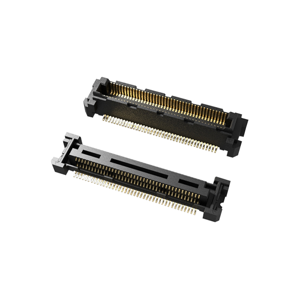
Figure 1: Y0510 Series 0.8mm pitch high-speed board-to-board connector — optimized for high-density SMT PCB stacking applications.
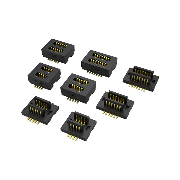
Figure 2: Y0517 Series 0.8mm pitch high-speed board-to-board connector — enhanced design for demanding signal integrity and multi-pin applications.
1. Rated Current — Match Power Requirements, Eliminate Thermal Risks
Rated current is the foundation of long-term connector reliability, directly determining the power delivery capability of each contact. Selection must balance single-pin current-carrying capacity against the total system power budget — avoiding both over-engineering ('overqualified connector') and under-specification ('thermal overload').
Standard 0.8mm pitch high-speed board-to-board connectors typically offer a rated current range of 0.3A ~ 0.8A per pin (dependent on contact material and geometry). Consumer electronics commonly use the 0.3A ~ 0.5A tier, while industrial equipment and high-end terminals, with their higher power demands, gravitate toward 0.5A ~ 0.8A models.
Core selection rule: Apply a 20% ~ 30% current margin. If the actual single-pin load in your design is 0.4A, specify a connector rated at ≥0.5A per pin. This headroom prevents long-term contact oxidation and performance degradation caused by sustained thermal stress.
2. Transmission Speed — Align with Signal Specifications, Preserve High-Speed Integrity
The defining advantage of high-speed board-to-board connectors is their ability to support multi-gigabit data rates. Selection must precisely match the target signal protocol and data rate, with particular attention to controlled impedance and cross-talk suppression.
Current mainstream 0.8mm pitch products support transmission rates from 10 Gbps to 32 Gbps+. Premium models are qualified for PCIe Gen4/Gen5 and USB 3.1 Gen2 standards, meeting the most demanding high-speed data transport requirements.
Selection checklist:
- Identify signal type: Determine the exact protocol — PCIe, MIPI, SATA, etc. — and select a connector rated for that interface's data rate.
- Prioritize differential pair construction: Choose products with dedicated differential pair geometry and controlled impedance (e.g., differential 100Ω). This effectively reduces cross-talk, insertion loss, and return loss, preserving end-to-end signal integrity.
- EMI shielding for high-frequency applications: For 5G, server, and other high-frequency deployments, select models with integrated metal shielding cages or coplanar ground structures to suppress electromagnetic interference (EMI).
3. PIN Count — Balance Interface Needs, Density, and Scalability
The PIN count directly determines the number of available signal and power channels. Selection must consider the PCB interface layout, signal routing requirements, available mounting footprint, and wiring density constraints simultaneously.
0.8mm pitch high-speed board-to-board connectors span a wide PIN count range. Standard configurations run from 20 to 200 positions, with some product families extending from 4 to as many as 440 positions for maximum flexibility.
Application-based guidance:
- Consumer electronics (TWS earbuds, foldable smartphones) — with ultra-compact enclosures — typically use 20 ~ 64 position connectors.
- Industrial equipment and servers requiring multi-channel throughput commonly adopt 80 ~ 200+ position configurations.
- Reserve 1 ~ 2 spare PINs for future board revisions or fault isolation. Align the final PIN count with the PCB routing layout to avoid wasted board area from unused positions.
4. Structural Design — Adapt to Installation Environment, Enhance Assembly & Reliability
Mechanical design directly affects installation ease, connection stability, and environmental suitability. Three mechanical factors dominate the selection decision: stack height, mounting style, and retention features.
1. Stack Height:
Mainstream stack heights range from 5 mm to 20 mm (in 1 mm increments), selectable based on the inter-board spacing in your enclosure. For parallel mezzanine stacking applications, free-height series connectors support 4 ~ 8 mm adjustable board-to-board distances, accommodating diverse mechanical design requirements.
2. Mounting Style:
SMT (Surface Mount Technology) is the dominant termination method, compatible with automated pick-and-place assembly and RoHS-compliant lead-free reflow processes for high-volume production efficiency. Select product families also support vertical right-angle mounting to serve different PCB orientation requirements.
3. Retention & Alignment Features:
Prioritize connectors with polarization/keying features to prevent reverse-mating damage to both the connector and PCB. Locking latch or floating designs (floating range up to ±0.6 mm) enhance mating retention in high-vibration environments while reducing blind-mate assembly cost and risk. Additionally, connector housings are predominantly molded from LCP thermoplastic, offering high-temperature endurance and UL94 V-0 flame retardancy, rated for -40°C to +125°C wide-temperature operation to satisfy diverse application environments.
5. Key Electrical Performance — Fortify the Stable Transmission Baseline
Beyond rated current, critical electrical parameters — contact resistance, insulation resistance, and dielectric withstanding voltage — directly govern connector stability and safety. Selection must be validated against industry standards and the target equipment's electrical requirements.
Core electrical performance benchmarks (aligned with mainstream industry standards):
- Contact Resistance: Initial maximum ≤30 mΩ; post-service change ≤20 mΩ. Lower contact resistance means lower signal transmission loss — elevated contact resistance from poor mating can cause intermittent signal dropouts.
- Insulation Resistance: ≥500 MΩ (both initial and post-service, measured at 500 VDC). High insulation resistance prevents leakage current, short circuits, and latent safety hazards, protecting overall equipment integrity.
- Dielectric Withstanding Voltage: 500 VAC for 1 minute with no flashover or surface discharge; leakage current ≤5 mA. This validates the connector's insulation reliability under high-voltage stress, confirming suitability for elevated-voltage operating environments.
6. Summary — A Structured Approach to 0.8mm B2B Connector Selection
Selecting the optimal 0.8mm pitch high-speed board-to-board connector is a multi-dimensional engineering decision. By systematically evaluating the five dimensions outlined above — rated current with adequate margin, transmission speed with impedance control, PIN count with future scalability, structural design with environmental suitability, and electrical performance with safety margin — design engineers can confidently identify the connector that maximizes both signal integrity and long-term field reliability. For application-specific recommendations, custom connector sourcing, or technical datasheets, our interconnect specialists are ready to support your next design.
Request 0.8mm B2B Connector Samples & Selection Support
●10~32Gbps+ High-Speed Series
●0.3A~0.8A Per Pin Rating
●Cost-Effective Cross-Reference
●Free Samples & Datasheets
0.8mm Pitch High-Speed Board-to-Board Connector Selection Guide — 5 Key Dimensions
Time: 2026-06-16 17:12:49
In 5G communications, high-performance computing, industrial control, and automotive electronics, 0.8mm pitch board-to-board connectors have emerged as the preferred interconnect solution where PCB real estate is constrained but high-speed signal integrity is non-negotiable. Their winning formula — high speed, high density, and high reliability — makes them indispensable. However, with a broad portfolio of available models, how do engineers quickly identify the optimal connector for their design? This article breaks down the selection process across five critical dimensions: rated current, transmission speed, PIN count, structural design, and key electrical performance.
Figure 1: Y0510 Series 0.8mm pitch high-speed board-to-board connector — optimized for high-density SMT PCB stacking applications.
Figure 2: Y0517 Series 0.8mm pitch high-speed board-to-board connector — enhanced design for demanding signal integrity and multi-pin applications.
1. Rated Current — Match Power Requirements, Eliminate Thermal Risks
Rated current is the foundation of long-term connector reliability, directly determining the power delivery capability of each contact. Selection must balance single-pin current-carrying capacity against the total system power budget — avoiding both over-engineering ('overqualified connector') and under-specification ('thermal overload').
Standard 0.8mm pitch high-speed board-to-board connectors typically offer a rated current range of 0.3A ~ 0.8A per pin (dependent on contact material and geometry). Consumer electronics commonly use the 0.3A ~ 0.5A tier, while industrial equipment and high-end terminals, with their higher power demands, gravitate toward 0.5A ~ 0.8A models.
Core selection rule: Apply a 20% ~ 30% current margin. If the actual single-pin load in your design is 0.4A, specify a connector rated at ≥0.5A per pin. This headroom prevents long-term contact oxidation and performance degradation caused by sustained thermal stress.
2. Transmission Speed — Align with Signal Specifications, Preserve High-Speed Integrity
The defining advantage of high-speed board-to-board connectors is their ability to support multi-gigabit data rates. Selection must precisely match the target signal protocol and data rate, with particular attention to controlled impedance and cross-talk suppression.
Current mainstream 0.8mm pitch products support transmission rates from 10 Gbps to 32 Gbps+. Premium models are qualified for PCIe Gen4/Gen5 and USB 3.1 Gen2 standards, meeting the most demanding high-speed data transport requirements.
Selection checklist:
- Identify signal type: Determine the exact protocol — PCIe, MIPI, SATA, etc. — and select a connector rated for that interface's data rate.
- Prioritize differential pair construction: Choose products with dedicated differential pair geometry and controlled impedance (e.g., differential 100Ω). This effectively reduces cross-talk, insertion loss, and return loss, preserving end-to-end signal integrity.
- EMI shielding for high-frequency applications: For 5G, server, and other high-frequency deployments, select models with integrated metal shielding cages or coplanar ground structures to suppress electromagnetic interference (EMI).
3. PIN Count — Balance Interface Needs, Density, and Scalability
The PIN count directly determines the number of available signal and power channels. Selection must consider the PCB interface layout, signal routing requirements, available mounting footprint, and wiring density constraints simultaneously.
0.8mm pitch high-speed board-to-board connectors span a wide PIN count range. Standard configurations run from 20 to 200 positions, with some product families extending from 4 to as many as 440 positions for maximum flexibility.
Application-based guidance:
- Consumer electronics (TWS earbuds, foldable smartphones) — with ultra-compact enclosures — typically use 20 ~ 64 position connectors.
- Industrial equipment and servers requiring multi-channel throughput commonly adopt 80 ~ 200+ position configurations.
- Reserve 1 ~ 2 spare PINs for future board revisions or fault isolation. Align the final PIN count with the PCB routing layout to avoid wasted board area from unused positions.
4. Structural Design — Adapt to Installation Environment, Enhance Assembly & Reliability
Mechanical design directly affects installation ease, connection stability, and environmental suitability. Three mechanical factors dominate the selection decision: stack height, mounting style, and retention features.
1. Stack Height:
Mainstream stack heights range from 5 mm to 20 mm (in 1 mm increments), selectable based on the inter-board spacing in your enclosure. For parallel mezzanine stacking applications, free-height series connectors support 4 ~ 8 mm adjustable board-to-board distances, accommodating diverse mechanical design requirements.
2. Mounting Style:
SMT (Surface Mount Technology) is the dominant termination method, compatible with automated pick-and-place assembly and RoHS-compliant lead-free reflow processes for high-volume production efficiency. Select product families also support vertical right-angle mounting to serve different PCB orientation requirements.
3. Retention & Alignment Features:
Prioritize connectors with polarization/keying features to prevent reverse-mating damage to both the connector and PCB. Locking latch or floating designs (floating range up to ±0.6 mm) enhance mating retention in high-vibration environments while reducing blind-mate assembly cost and risk. Additionally, connector housings are predominantly molded from LCP thermoplastic, offering high-temperature endurance and UL94 V-0 flame retardancy, rated for -40°C to +125°C wide-temperature operation to satisfy diverse application environments.
5. Key Electrical Performance — Fortify the Stable Transmission Baseline
Beyond rated current, critical electrical parameters — contact resistance, insulation resistance, and dielectric withstanding voltage — directly govern connector stability and safety. Selection must be validated against industry standards and the target equipment's electrical requirements.
Core electrical performance benchmarks (aligned with mainstream industry standards):
- Contact Resistance: Initial maximum ≤30 mΩ; post-service change ≤20 mΩ. Lower contact resistance means lower signal transmission loss — elevated contact resistance from poor mating can cause intermittent signal dropouts.
- Insulation Resistance: ≥500 MΩ (both initial and post-service, measured at 500 VDC). High insulation resistance prevents leakage current, short circuits, and latent safety hazards, protecting overall equipment integrity.
- Dielectric Withstanding Voltage: 500 VAC for 1 minute with no flashover or surface discharge; leakage current ≤5 mA. This validates the connector's insulation reliability under high-voltage stress, confirming suitability for elevated-voltage operating environments.
6. Summary — A Structured Approach to 0.8mm B2B Connector Selection
Selecting the optimal 0.8mm pitch high-speed board-to-board connector is a multi-dimensional engineering decision. By systematically evaluating the five dimensions outlined above — rated current with adequate margin, transmission speed with impedance control, PIN count with future scalability, structural design with environmental suitability, and electrical performance with safety margin — design engineers can confidently identify the connector that maximizes both signal integrity and long-term field reliability. For application-specific recommendations, custom connector sourcing, or technical datasheets, our interconnect specialists are ready to support your next design.
Request 0.8mm B2B Connector Samples & Selection Support
●10~32Gbps+ High-Speed Series
●0.3A~0.8A Per Pin Rating
●Cost-Effective Cross-Reference
●Free Samples & Datasheets
Other Articles
-

Role of 32.768 kHz in Circuit Design
-
SiTime Automotive Oscillators
-
The Role of 32.768kHz in Circuits
-
Epson RTC modules solve three major pain points of ioT
-
Examine the cost and design considerations of crystals and oscillators
-
11.0592MHz Crystal Oscillator: The "Heart" of the Computer Motherboard?
-
Exploring how YXC oscillators show their skills to help with AI servers
-
Lessons from the Middle East Events — The Importance of Localization!
-
Good News: YQM won Epson's 2023 New Market Development Award !!!
-
YXC Active Differential Programmable Crystal Oscillator Supports 5G Base Station Applications


Copyright By © YQM ELECTRONICS INTL LIMITED SITEMAP
Email: sales@yqmec.com

点击右上角
分享给朋友吧


