
electronica 2026: Clock Tree & Power BOM Essentials
Time: 2026-11-10 17:18:56
electronica 2026: What AI, Resilience and Efficiency Ask of Your BOM
electronica 2026 opens today in Munich — November 10–13, 18 halls, roughly 3,500 exhibitors — and three themes run across every banner: AI, network resilience and energy efficiency, next to a new edge lab LIVE! and a Sensor Pavilion.
Here is the part the banners leave out. Each theme lands on your bill of materials as a small group of under-rated foundation parts: the reference clock, the power magnetics and the current sensor. They rarely appear in a keynote, and they are usually what decides whether a build ships on schedule.
1. The AI theme is a timing and power problem before it is a compute problem
AI racks are dense, hot and clock-hungry. Two consequences reach the BOM.
First, the jitter budget. High-speed serial links leave very little margin, so the reference clock has to hold frequency through fan-driven airflow, load steps and thermal gradients. That pushes designs toward low-jitter differential oscillators and temperature-compensated references — see our Super-TCXO and crystal ranges — instead of a plain crystal plus a driver stage.
Second, the power stage. Higher-voltage DC distribution and GaN intermediate bus converters move very high current per rack, which makes the inductor the bottleneck before the MOSFET does: saturation current (Isat), DC resistance (DCR) and temperature rise decide how much of the conversion chain you can actually use.
- Jitter and phase noise at the real link rate, not a catalogue typical.
- Frequency stability across the thermal profile inside the enclosure.
- Isat, DCR and temperature rise at the ripple current you will run, through power inductors qualified for the load profile.
- Availability now — not after the design freeze.
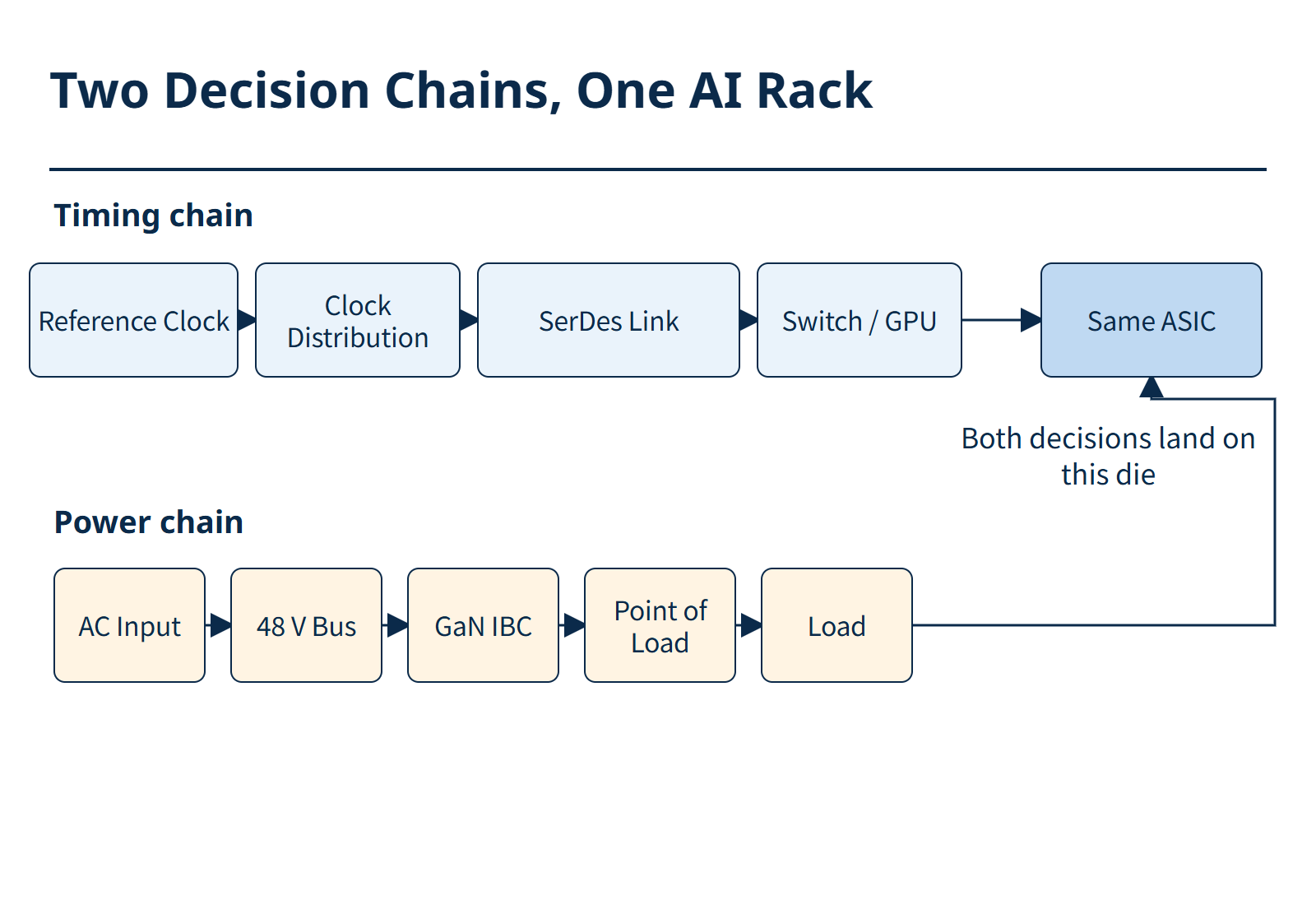
Figure 1. Two decision chains in one AI rack: the timing chain above, the power chain below, both landing on the same ASIC at the right. They are decisions on one BOM, taken at the same time.
Which reference to pick is a three-way decision, not a brand preference. A plain crystal plus a driver stage is still the cheapest answer when the enclosure is thermally stable and the serial link is short. A differential oscillator earns its price once the link rate climbs and the jitter budget stops being generous. A compensated device is the right answer when temperature swing is the dominant error term — fan-driven airflow inside a rack, a pole-mounted box in the sun, an outdoor cabinet. Getting this wrong is rarely a dramatic failure; it is a quiet loss of margin that reappears as retries two quarters later.
2. Network resilience is, in practice, a holdover specification
Resilience means staying synchronised when the network does not cooperate. 5G-Advanced and O-RAN deployments keep tightening sync budgets — industry reports put targets near ±130 ns in demanding fronthaul cases — while PTP carries a growing share of new builds. Once GNSS interference and denial are treated as normal operating conditions, local holdover stops being a nice-to-have.
That turns into oscillator requirements: OCXO and Super-TCXO classes with a documented holdover figure, ageing data and temperature behaviour you can put into a budget. Take the number from the datasheet, not from a booth slide.
- Holdover duration and the phase error at the end of it.
- Ageing per year and stability over the operating temperature range.
- Behaviour during and after a GNSS outage, including re-lock time.
- Power consumption — holdover in a pole-mounted unit is a thermal problem too.
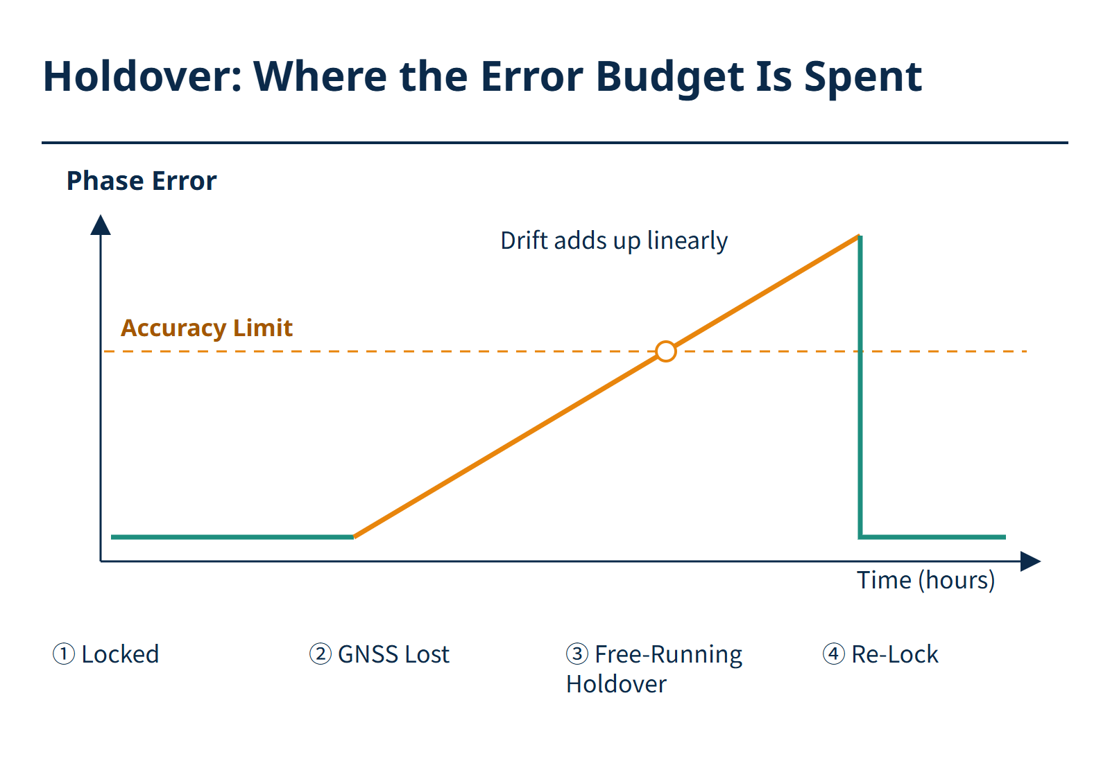
Figure 2. A holdover event read against the accuracy limit. The error stays flat while locked, ramps linearly once GNSS is lost, then snaps back on re-lock — the budget is spent the instant the ramp crosses the limit.
Budgeting holdover is arithmetic, not marketing. Three terms dominate: the offset at the moment the reference is locked, the drift accumulated over the holdover window, and ageing since the last calibration. Add them at the worst-case temperature, then compare the sum against the phase error your air interface tolerates at the end of the window. If the sum crosses that limit halfway through, the holdover duration you were quoted is half of what you assume.
3. Energy efficiency is a chain, not a single switch
Efficiency gets discussed as one wide-bandgap device. In practice it is a chain. A cleaner SiC or GaN stage needs an accurate current sensor to prove its losses, a stable low-noise clock for the digital control loop, and a power inductor that does not cook itself under ripple. The 48 V zonal architectures credited with up to roughly 75% less wiring weight only pay off when the local timing, sensing and magnetics are qualified for the new thermal and EMI envelope.
- Conversion efficiency across the real load profile, light load included.
- Inductor temperature rise at maximum ambient, not at room temperature.
- Sensor accuracy, bandwidth and drift — Hall-effect current sensors are only as good as their temperature behaviour.
- EMI behaviour after the switching frequency goes up.
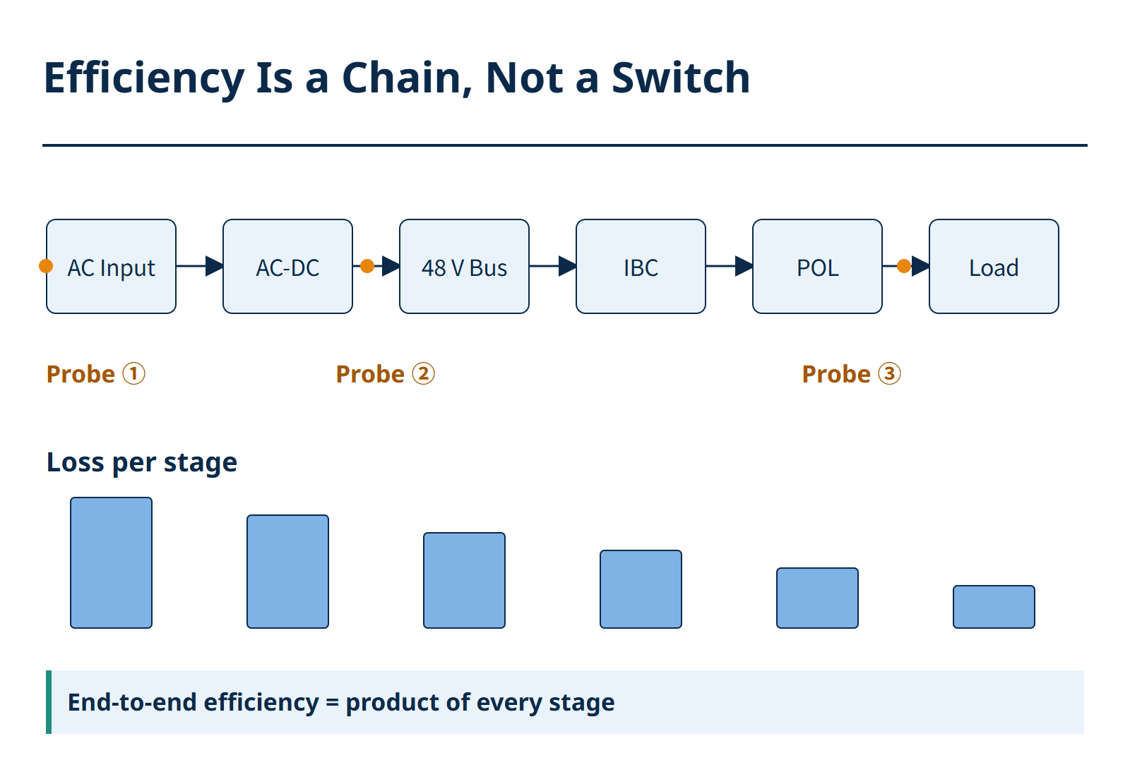
Figure 3. Efficiency is a chain, not a switch. The shrinking bars are the loss left at each stage, and the weakest stage decides the end-to-end figure.
Locating the loss is easier than removing it. Measure at three points — input, after the first conversion stage, at the point of load — and the chain shows where the loss sits. A stage that is efficient at full load and poor at ten percent load is usually a control-loop or magnetics problem, not a semiconductor problem. That is why the inductor and the current sensor keep appearing in efficiency conversations: they set the shape of the curve, not only its peak.
| Component | What decides the loss | Where it bites |
|---|---|---|
| Power inductor | DCR at operating temperature; core loss at your ripple | Light load and high ambient |
| Current sensor | Offset drift and bandwidth | Loop stability, loss measurement |
| Reference clock | Jitter at the switching harmonic | EMI and control-loop timing |
4. A five-line checklist for the show floor
A trade fair is efficient for exactly one thing: qualifying parts you have already shortlisted. Bring the BOM, not a shopping list. At our stand — Hall B5, 559-1 — the useful conversation is a five-line comparison per candidate part.
| Parameter | Ask for | Why it matters |
|---|---|---|
| Jitter / phase noise | Measured at your actual link rate | Catalogue typicals hide the integration band |
| Frequency stability | Over your real thermal profile | Rack airflow is not a lab bench |
| Isat / DCR | At the ripple current you will run | Datasheet Isat is often quoted at roll-off |
| Holdover | A documented figure with conditions | A number without conditions is not a spec |
| Lead time | Current, in writing | Q4 allocations decide the schedule |
SiTime's own exhibit (C2.453) is a short walk away and worth a visit as an industry signal — that is the manufacturer's stand, not ours. Our engineering contact point during the show is Hall B5, 559-1.
5. Frequently asked questions
What does a trade-show theme have to do with a single component? A theme is shorthand for a set of specifications. "AI" means jitter, thermal stability and current density; "resilience" means holdover; "efficiency" means losses across the load range. The theme tells you which specs to prioritise this sourcing cycle.
Why do compensated oscillators keep appearing in data-centre discussions? Because airflow and load steps cause temperature drift, drift consumes jitter margin, and jitter margin is throughput on a high-speed link. A compensated reference keeps the budget intact without re-spinning the thermal design.
We buy in small and mid volumes. Is the show useful for us? Yes, if you use it for qualification rather than catalogue collection. Bring three or four candidate parts, ask for the datasheet conditions behind each headline number, and confirm current stock and lead time in writing before you leave.
6. Where to find us during the show
At electronica 2026 we are at Hall B5, 559-1 with datasheets and samples for timing, power magnetics and current sensing. Timing parts come from EPSON and SiTime, magnetics from Sunlord, and current sensing from Honeywell; our own YXC-branded timing families sit alongside them as a second-source option. Bring your BOM and we will map each theme to the parameters you need to qualify — and tell you honestly which parts we can support from stock.
Meet Us at electronica 2026 · Hall B5, 559-1
●Nov 10–13, 2026 · Messe München
●Hall B5, 559-1
●Timing · Magnetics · Current sensing
●Samples & datasheets
●BOM qualification review
electronica 2026: Clock Tree & Power BOM Essentials
Time: 2026-11-10 17:18:56
electronica 2026: What AI, Resilience and Efficiency Ask of Your BOM
electronica 2026 opens today in Munich — November 10–13, 18 halls, roughly 3,500 exhibitors — and three themes run across every banner: AI, network resilience and energy efficiency, next to a new edge lab LIVE! and a Sensor Pavilion.
Here is the part the banners leave out. Each theme lands on your bill of materials as a small group of under-rated foundation parts: the reference clock, the power magnetics and the current sensor. They rarely appear in a keynote, and they are usually what decides whether a build ships on schedule.
1. The AI theme is a timing and power problem before it is a compute problem
AI racks are dense, hot and clock-hungry. Two consequences reach the BOM.
First, the jitter budget. High-speed serial links leave very little margin, so the reference clock has to hold frequency through fan-driven airflow, load steps and thermal gradients. That pushes designs toward low-jitter differential oscillators and temperature-compensated references — see our Super-TCXO and crystal ranges — instead of a plain crystal plus a driver stage.
Second, the power stage. Higher-voltage DC distribution and GaN intermediate bus converters move very high current per rack, which makes the inductor the bottleneck before the MOSFET does: saturation current (Isat), DC resistance (DCR) and temperature rise decide how much of the conversion chain you can actually use.
- Jitter and phase noise at the real link rate, not a catalogue typical.
- Frequency stability across the thermal profile inside the enclosure.
- Isat, DCR and temperature rise at the ripple current you will run, through power inductors qualified for the load profile.
- Availability now — not after the design freeze.
Figure 1. Two decision chains in one AI rack: the timing chain above, the power chain below, both landing on the same ASIC at the right. They are decisions on one BOM, taken at the same time.
Which reference to pick is a three-way decision, not a brand preference. A plain crystal plus a driver stage is still the cheapest answer when the enclosure is thermally stable and the serial link is short. A differential oscillator earns its price once the link rate climbs and the jitter budget stops being generous. A compensated device is the right answer when temperature swing is the dominant error term — fan-driven airflow inside a rack, a pole-mounted box in the sun, an outdoor cabinet. Getting this wrong is rarely a dramatic failure; it is a quiet loss of margin that reappears as retries two quarters later.
2. Network resilience is, in practice, a holdover specification
Resilience means staying synchronised when the network does not cooperate. 5G-Advanced and O-RAN deployments keep tightening sync budgets — industry reports put targets near ±130 ns in demanding fronthaul cases — while PTP carries a growing share of new builds. Once GNSS interference and denial are treated as normal operating conditions, local holdover stops being a nice-to-have.
That turns into oscillator requirements: OCXO and Super-TCXO classes with a documented holdover figure, ageing data and temperature behaviour you can put into a budget. Take the number from the datasheet, not from a booth slide.
- Holdover duration and the phase error at the end of it.
- Ageing per year and stability over the operating temperature range.
- Behaviour during and after a GNSS outage, including re-lock time.
- Power consumption — holdover in a pole-mounted unit is a thermal problem too.
Figure 2. A holdover event read against the accuracy limit. The error stays flat while locked, ramps linearly once GNSS is lost, then snaps back on re-lock — the budget is spent the instant the ramp crosses the limit.
Budgeting holdover is arithmetic, not marketing. Three terms dominate: the offset at the moment the reference is locked, the drift accumulated over the holdover window, and ageing since the last calibration. Add them at the worst-case temperature, then compare the sum against the phase error your air interface tolerates at the end of the window. If the sum crosses that limit halfway through, the holdover duration you were quoted is half of what you assume.
3. Energy efficiency is a chain, not a single switch
Efficiency gets discussed as one wide-bandgap device. In practice it is a chain. A cleaner SiC or GaN stage needs an accurate current sensor to prove its losses, a stable low-noise clock for the digital control loop, and a power inductor that does not cook itself under ripple. The 48 V zonal architectures credited with up to roughly 75% less wiring weight only pay off when the local timing, sensing and magnetics are qualified for the new thermal and EMI envelope.
- Conversion efficiency across the real load profile, light load included.
- Inductor temperature rise at maximum ambient, not at room temperature.
- Sensor accuracy, bandwidth and drift — Hall-effect current sensors are only as good as their temperature behaviour.
- EMI behaviour after the switching frequency goes up.
Figure 3. Efficiency is a chain, not a switch. The shrinking bars are the loss left at each stage, and the weakest stage decides the end-to-end figure.
Locating the loss is easier than removing it. Measure at three points — input, after the first conversion stage, at the point of load — and the chain shows where the loss sits. A stage that is efficient at full load and poor at ten percent load is usually a control-loop or magnetics problem, not a semiconductor problem. That is why the inductor and the current sensor keep appearing in efficiency conversations: they set the shape of the curve, not only its peak.
| Component | What decides the loss | Where it bites |
|---|---|---|
| Power inductor | DCR at operating temperature; core loss at your ripple | Light load and high ambient |
| Current sensor | Offset drift and bandwidth | Loop stability, loss measurement |
| Reference clock | Jitter at the switching harmonic | EMI and control-loop timing |
4. A five-line checklist for the show floor
A trade fair is efficient for exactly one thing: qualifying parts you have already shortlisted. Bring the BOM, not a shopping list. At our stand — Hall B5, 559-1 — the useful conversation is a five-line comparison per candidate part.
| Parameter | Ask for | Why it matters |
|---|---|---|
| Jitter / phase noise | Measured at your actual link rate | Catalogue typicals hide the integration band |
| Frequency stability | Over your real thermal profile | Rack airflow is not a lab bench |
| Isat / DCR | At the ripple current you will run | Datasheet Isat is often quoted at roll-off |
| Holdover | A documented figure with conditions | A number without conditions is not a spec |
| Lead time | Current, in writing | Q4 allocations decide the schedule |
SiTime's own exhibit (C2.453) is a short walk away and worth a visit as an industry signal — that is the manufacturer's stand, not ours. Our engineering contact point during the show is Hall B5, 559-1.
5. Frequently asked questions
What does a trade-show theme have to do with a single component? A theme is shorthand for a set of specifications. "AI" means jitter, thermal stability and current density; "resilience" means holdover; "efficiency" means losses across the load range. The theme tells you which specs to prioritise this sourcing cycle.
Why do compensated oscillators keep appearing in data-centre discussions? Because airflow and load steps cause temperature drift, drift consumes jitter margin, and jitter margin is throughput on a high-speed link. A compensated reference keeps the budget intact without re-spinning the thermal design.
We buy in small and mid volumes. Is the show useful for us? Yes, if you use it for qualification rather than catalogue collection. Bring three or four candidate parts, ask for the datasheet conditions behind each headline number, and confirm current stock and lead time in writing before you leave.
6. Where to find us during the show
At electronica 2026 we are at Hall B5, 559-1 with datasheets and samples for timing, power magnetics and current sensing. Timing parts come from EPSON and SiTime, magnetics from Sunlord, and current sensing from Honeywell; our own YXC-branded timing families sit alongside them as a second-source option. Bring your BOM and we will map each theme to the parameters you need to qualify — and tell you honestly which parts we can support from stock.
Meet Us at electronica 2026 · Hall B5, 559-1
●Nov 10–13, 2026 · Messe München
●Hall B5, 559-1
●Timing · Magnetics · Current sensing
●Samples & datasheets
●BOM qualification review
Other Articles
-

electronica 2026: Clock Tree & Power BOM Essentials
-
Base Station Power MOSFET Selection: 8 NCE MOSFETs from 650V PFC to 48V Bus
-
Epson XV7021BB Gyroscope: QMEMS Angular Rate Sensor for UAV & Industrial AHRS
-
Epson RA4803SA RTC: Ultra-Low-Power Real-Time Clock for Portable & Industrial
-
YQM FPC Connector Selection Guide: 0.5mm Pitch ZIF for Consumer & Wearable Devices
-
YSO510TP Drone TCXO: ±0.5 ppm from -40°C to +85°C
-
SiTime MEMS Timing for Aerospace & Defense: Precision PNT in Extreme Environments
-
Sunlord WCX Ultra-Low-Voltage Molded Power Inductors for 800G/1.6T AI Optical Modules
-
SiTime PNT Timing Foundation: Why Precision Oscillators Define Modern Navigation
-
YQ8563: Drop-In Low-Power RTC Replacement for NXP PCF8563


Copyright By © YQM ELECTRONICS INTL LIMITED SITEMAP
Email: sales@yqmec.com

点击右上角
分享给朋友吧


