
Sunlord PoC Inductors for Automotive GMSL2 Camera Links
Time: 2026-11-20 16:52:36
Sunlord PoC Inductors for Automotive GMSL2 Camera Links
A modern ADAS camera receives power and returns video over a single coaxial cable. Power-over-Coax (PoC) superimposes DC power, high-speed video and control signalling on the same conductor, which reduces harness weight and connector count — but it also puts the DC feed directly on the signal path. Any leakage of the GMSL2 waveform into the power rail closes the received eye and appears as noise in the image. Sunlord's AWL-FS, AWL-FP and AMWPH/ASWPA families form a three-stage PoC filter, and selected current-rated solutions are certified by ADI for GMSL2 SerDes and listed in ADI's GMSL2 Hardware Design and Validation Guide.
Explore the Sunlord brand page, the automotive PoC circuit category and the full inductor range.
1. Why a PoC Filter Decides Image Quality
GMSL2 carries video at up to 6 Gbit/s and supports cameras up to 8 MP. A level-2 vehicle typically uses five to eight cameras, and level-3 designs use more than eight. In a PoC harness, the ECU sends DC power up the same coax that returns the camera's serial data. The supply output is a low-impedance node, so without a filter the high-frequency content sees a short and leaks into the power line; the signal line is then mismatched, and the link loses margin.
The fix is an inductor network in series with the DC feed. It must present a high impedance across the entire GMSL2 band — forward and reverse channels — while passing DC with low loss. Sunlord specifies a target above 1 kΩ for the PoC filter, and no single inductor holds that impedance from a few MHz to several GHz. The filter therefore uses cascaded stages, each covering part of the band.
- Band coverage: forward and reverse channels of the GMSL2 link.
- Impedance: above 1 kΩ across the filter band.
- DC path: low DCR to keep I²R loss and self-heating small.
- Current: sized for the link current at 105 °C, not only at 25 °C.
- Qualification: AEC-Q200 for automotive camera modules.
2. The Three-Stage Filter Architecture
Sunlord splits the filter into three functional blocks. Each block uses a different winding and core so that the impedance stays high where the previous stage begins to fall.
- Stage 1 — AWL-FS (1608): high-frequency impedance, placed closest to the coaxial node.
- Stage 2 — AWL-FP (3225): mid- and low-frequency impedance; selected parts reach 12 kΩ.
- Stage 3 — AMWPH/ASWPA: low-frequency filtering and the link's DC current.
The order matters: the high-frequency stage faces the RF node, while the larger low-frequency part sits toward the DC supply. Figure 1 shows the signal and power branches around the coax node.
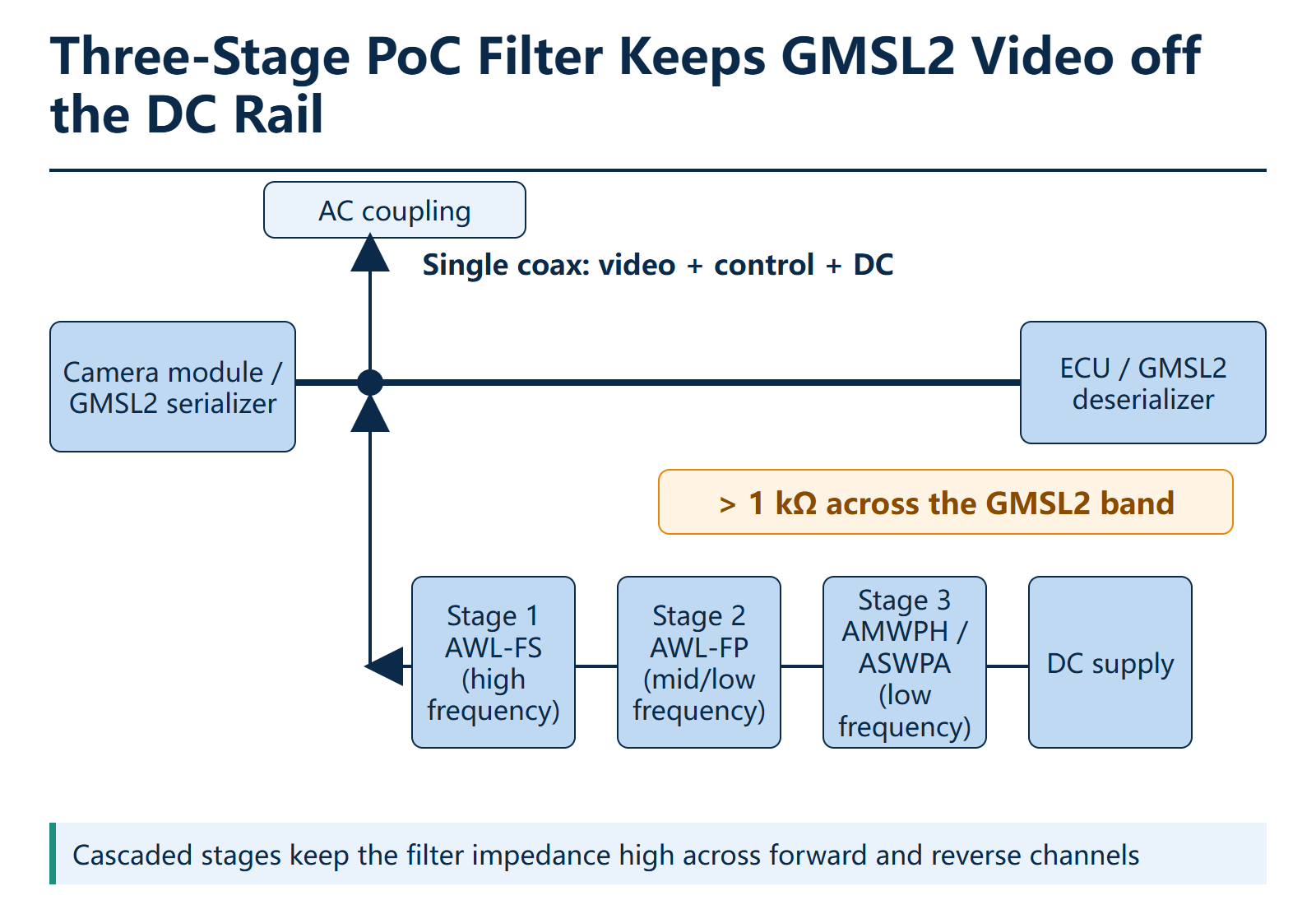
Figure 1: Three-stage PoC filter between the coax node and the DC supply. High-frequency AWL-FS sits closest to the cable; AWL-FP and AMWPH/ASWPA follow toward the supply.
3. Stage 1 — AWL-FS: High-Frequency Filtering in 1608
AWL-FS is a wire-wound ferrite chip inductor in 1608 (0603, 1.6×0.8×0.8 mm). The family covers 100–650 nH with DCR from 0.100 Ω to 0.520 Ω and a rated current of 430–1000 mA. Its broadband high impedance filters video noise from MHz to GHz while the same part carries the DC feed. The series is AEC-Q200 qualified.
In the ADI-certified designs, three parts appear at L1, directly at the coax node: AWL1608FSR65JTFM01 (650 nH), AWL1608FSR39JTFM01 (390 nH) and AWL1608FSR21MTFY01 (210 nH). The lower inductance values are used where the link needs a higher self-resonant frequency.
Product family: AWL1608FS-M01.
4. Stage 2 — AWL-FP: Mid/Low-Frequency Filtering in 3225
AWL-FP is a 3225 wire-wound ferrite inductor (3.2×2.5×2.3 mm) covering 2.2–47 µH. Key ratings are SRF 30–200 MHz, DCR 0.19–0.90 Ω, saturation current 300–1000 mA and RMS current 500–1000 mA. The series is AEC-Q200 qualified.
The 4.7 µH member, AWL3225FP4R7MTF, reaches 12 kΩ in the certified 600 mA solution — the highest impedance in the family. The 10 µH AWL3225FP100MTF is specified at 2 kΩ in the 400 mA and 500 mA designs, and the 2.2 µH AWL3225FP2R2MTF is used in the 800 mA solution.
Product family: AWL3225-FP.
5. Stage 3 — AMWPH/ASWPA: Low-Frequency, High-Current Filtering
The third stage handles the low-frequency end and carries the full link current. The AMWPH and ASWPA families span 0.33–150 µH in 3015, 4018, 4035 and 5030 packages, with saturation currents in the multi-amp range: up to 2.75 A in the 3015 class, 9.8 A in the 4035 class and 15 A in the 5030 class. Selected AMWPH3015S150MT parts provide up to 1.95 A, which gives current headroom in the 600 mA certified solution.
Because this stage is closest to the DC supply, its DCR has the largest effect on I²R loss. The 4035 family starts at 8 mΩ and the 5030 family at 8.1 mΩ typical, so the filter can carry link current without a measurable thermal penalty.
Product families: AMWPH3015S, AMWPH5030S and ASWPA4035S.
6. ADI-Certified Reference Configurations
Sunlord's current-rated PoC solutions are certified by ADI for GMSL2 SerDes and added to ADI's official GMSL2 Hardware Design and Validation Guide. The combinations below are a practical starting point for a new camera module; always confirm the exact ordering code, impedance and datasheet for your production part.
| Link current | ADI circuit | L1 — high frequency | L2 — mid/low frequency | L3 — low frequency | Notes |
|---|---|---|---|---|---|
| 300 mA | S-2L-300-0 | AWL1608FSR65JTFM01 (650 nH) | AWL3225FP470MTF (47 µH, 1.5 kΩ) | — | Two-inductor solution |
| 400 mA | S-3L-400-0 | AWL1608FSR39JTFM01 (390 nH) | AWL3225FP100MTF (10 µH, 2 kΩ) | ASWPA4035S101MT (100 µH, 1 kΩ) | 450 mA @105 °C |
| 500 mA | S-3L-500-0 | AWL1608FSR39JTFM01 (390 nH) | AWL3225FP100MTF (10 µH, 2 kΩ) | AMWPH4018S330MT (33 µH, 1 kΩ) | — |
| 600 mA | S-3L-600-0 | AWL1608FSR39JTFM01 (390 nH) | AWL3225FP4R7MTF (4.7 µH, 12 kΩ) | AMWPH3015S150MT (15 µH, 2 kΩ) | — |
| 800 mA | S-3L-800-0 | AWL1608FSR21MTFY01 (210 nH) | AWL3225FP2R2MTF (2.2 µH, 2 kΩ) | AMWPH5030S220MTY01 (22 µH, 2 kΩ) | 1000 mA @105 °C |
Note: “—” means the stage is not used in that certified solution. The 400 mA and 800 mA solutions carry additional current ratings of 450 mA and 1000 mA at 105 °C respectively. The certification list is published in ADI's GMSL2 Hardware Design and Validation Guide.
7. Selection Checklist for a GMSL2 Camera
Use the checklist below to translate a camera-module requirement into filter stages. Figure 2 summarises the same data as a selection matrix for quick review with the mechanical and thermal teams.
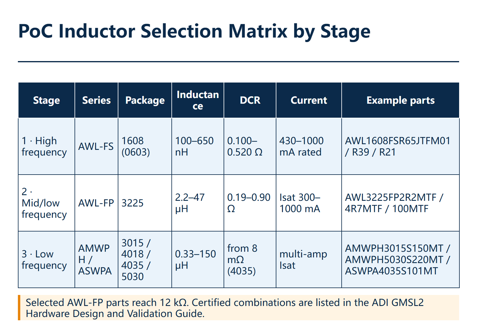
Figure 2: PoC inductor selection matrix by stage, package, inductance, DCR and current.
| Design item | What to verify | Recommended stage |
|---|---|---|
| Coax node | Highest frequency content; place the smallest package closest to the connector | AWL-FS, 1608 |
| Mid-band impedance | Target above 1 kΩ; selected AWL-FP parts reach 12 kΩ | AWL-FP, 3225 |
| Link current | Rated current at 105 °C with margin for transients | AMWPH / ASWPA |
| DC loss | Sum the DCR of all stages against the rail budget | Low-DCR members |
| Automotive qualification | Confirm AEC-Q200 on the exact ordering code | All three families |
| Certification | Start from an ADI S-xL reference for the link current | Certified solution |
| Board validation | Eye diagram, jitter and conducted emissions on the final PCB | Prototype |
For the wider power-inductor portfolio used around the camera ECU, see power inductors.
8. FAQ
Q: What does a PoC filter actually do?
A: It separates the DC supply from the high-speed video on the coax. The inductors pass DC to the camera but block the GMSL2 band from entering the power line.
Q: Why use three stages instead of one large inductor?
A: A single inductor cannot hold more than 1 kΩ from a few MHz to several GHz. Each stage covers a different band, so the cascade keeps the impedance high across the whole link.
Q: Are Sunlord PoC inductors AEC-Q200 qualified?
A: Yes, the AWL-FS, AWL-FP and AMWPH/ASWPA families are AEC-Q200 qualified. Confirm the qualification on the exact ordering code in the datasheet.
Q: Which solution should I start with for an 800 mA link?
A: The ADI-certified S-3L-800-0 uses AWL1608FSR21MTFY01, AWL3225FP2R2MTF and AMWPH5030S220MTY01, and is rated 1000 mA at 105 °C. Validate it on your own PCB before release.
Q: Can YQM supply samples and datasheets?
A: Yes. YQM ELECTRONICS supplies samples, full datasheets and FAE support for Sunlord PoC inductors.
Get Sunlord PoC Inductor Samples
Contact YQM ELECTRONICS for samples, datasheets and FAE support for GMSL2 camera and ADAS designs.
Contact YQM Customer ServiceSunlord PoC Inductors for Automotive GMSL2 Camera Links
Time: 2026-11-20 16:52:36
Sunlord PoC Inductors for Automotive GMSL2 Camera Links
A modern ADAS camera receives power and returns video over a single coaxial cable. Power-over-Coax (PoC) superimposes DC power, high-speed video and control signalling on the same conductor, which reduces harness weight and connector count — but it also puts the DC feed directly on the signal path. Any leakage of the GMSL2 waveform into the power rail closes the received eye and appears as noise in the image. Sunlord's AWL-FS, AWL-FP and AMWPH/ASWPA families form a three-stage PoC filter, and selected current-rated solutions are certified by ADI for GMSL2 SerDes and listed in ADI's GMSL2 Hardware Design and Validation Guide.
Explore the Sunlord brand page, the automotive PoC circuit category and the full inductor range.
1. Why a PoC Filter Decides Image Quality
GMSL2 carries video at up to 6 Gbit/s and supports cameras up to 8 MP. A level-2 vehicle typically uses five to eight cameras, and level-3 designs use more than eight. In a PoC harness, the ECU sends DC power up the same coax that returns the camera's serial data. The supply output is a low-impedance node, so without a filter the high-frequency content sees a short and leaks into the power line; the signal line is then mismatched, and the link loses margin.
The fix is an inductor network in series with the DC feed. It must present a high impedance across the entire GMSL2 band — forward and reverse channels — while passing DC with low loss. Sunlord specifies a target above 1 kΩ for the PoC filter, and no single inductor holds that impedance from a few MHz to several GHz. The filter therefore uses cascaded stages, each covering part of the band.
- Band coverage: forward and reverse channels of the GMSL2 link.
- Impedance: above 1 kΩ across the filter band.
- DC path: low DCR to keep I²R loss and self-heating small.
- Current: sized for the link current at 105 °C, not only at 25 °C.
- Qualification: AEC-Q200 for automotive camera modules.
2. The Three-Stage Filter Architecture
Sunlord splits the filter into three functional blocks. Each block uses a different winding and core so that the impedance stays high where the previous stage begins to fall.
- Stage 1 — AWL-FS (1608): high-frequency impedance, placed closest to the coaxial node.
- Stage 2 — AWL-FP (3225): mid- and low-frequency impedance; selected parts reach 12 kΩ.
- Stage 3 — AMWPH/ASWPA: low-frequency filtering and the link's DC current.
The order matters: the high-frequency stage faces the RF node, while the larger low-frequency part sits toward the DC supply. Figure 1 shows the signal and power branches around the coax node.
Figure 1: Three-stage PoC filter between the coax node and the DC supply. High-frequency AWL-FS sits closest to the cable; AWL-FP and AMWPH/ASWPA follow toward the supply.
3. Stage 1 — AWL-FS: High-Frequency Filtering in 1608
AWL-FS is a wire-wound ferrite chip inductor in 1608 (0603, 1.6×0.8×0.8 mm). The family covers 100–650 nH with DCR from 0.100 Ω to 0.520 Ω and a rated current of 430–1000 mA. Its broadband high impedance filters video noise from MHz to GHz while the same part carries the DC feed. The series is AEC-Q200 qualified.
In the ADI-certified designs, three parts appear at L1, directly at the coax node: AWL1608FSR65JTFM01 (650 nH), AWL1608FSR39JTFM01 (390 nH) and AWL1608FSR21MTFY01 (210 nH). The lower inductance values are used where the link needs a higher self-resonant frequency.
Product family: AWL1608FS-M01.
4. Stage 2 — AWL-FP: Mid/Low-Frequency Filtering in 3225
AWL-FP is a 3225 wire-wound ferrite inductor (3.2×2.5×2.3 mm) covering 2.2–47 µH. Key ratings are SRF 30–200 MHz, DCR 0.19–0.90 Ω, saturation current 300–1000 mA and RMS current 500–1000 mA. The series is AEC-Q200 qualified.
The 4.7 µH member, AWL3225FP4R7MTF, reaches 12 kΩ in the certified 600 mA solution — the highest impedance in the family. The 10 µH AWL3225FP100MTF is specified at 2 kΩ in the 400 mA and 500 mA designs, and the 2.2 µH AWL3225FP2R2MTF is used in the 800 mA solution.
Product family: AWL3225-FP.
5. Stage 3 — AMWPH/ASWPA: Low-Frequency, High-Current Filtering
The third stage handles the low-frequency end and carries the full link current. The AMWPH and ASWPA families span 0.33–150 µH in 3015, 4018, 4035 and 5030 packages, with saturation currents in the multi-amp range: up to 2.75 A in the 3015 class, 9.8 A in the 4035 class and 15 A in the 5030 class. Selected AMWPH3015S150MT parts provide up to 1.95 A, which gives current headroom in the 600 mA certified solution.
Because this stage is closest to the DC supply, its DCR has the largest effect on I²R loss. The 4035 family starts at 8 mΩ and the 5030 family at 8.1 mΩ typical, so the filter can carry link current without a measurable thermal penalty.
Product families: AMWPH3015S, AMWPH5030S and ASWPA4035S.
6. ADI-Certified Reference Configurations
Sunlord's current-rated PoC solutions are certified by ADI for GMSL2 SerDes and added to ADI's official GMSL2 Hardware Design and Validation Guide. The combinations below are a practical starting point for a new camera module; always confirm the exact ordering code, impedance and datasheet for your production part.
| Link current | ADI circuit | L1 — high frequency | L2 — mid/low frequency | L3 — low frequency | Notes |
|---|---|---|---|---|---|
| 300 mA | S-2L-300-0 | AWL1608FSR65JTFM01 (650 nH) | AWL3225FP470MTF (47 µH, 1.5 kΩ) | — | Two-inductor solution |
| 400 mA | S-3L-400-0 | AWL1608FSR39JTFM01 (390 nH) | AWL3225FP100MTF (10 µH, 2 kΩ) | ASWPA4035S101MT (100 µH, 1 kΩ) | 450 mA @105 °C |
| 500 mA | S-3L-500-0 | AWL1608FSR39JTFM01 (390 nH) | AWL3225FP100MTF (10 µH, 2 kΩ) | AMWPH4018S330MT (33 µH, 1 kΩ) | — |
| 600 mA | S-3L-600-0 | AWL1608FSR39JTFM01 (390 nH) | AWL3225FP4R7MTF (4.7 µH, 12 kΩ) | AMWPH3015S150MT (15 µH, 2 kΩ) | — |
| 800 mA | S-3L-800-0 | AWL1608FSR21MTFY01 (210 nH) | AWL3225FP2R2MTF (2.2 µH, 2 kΩ) | AMWPH5030S220MTY01 (22 µH, 2 kΩ) | 1000 mA @105 °C |
Note: “—” means the stage is not used in that certified solution. The 400 mA and 800 mA solutions carry additional current ratings of 450 mA and 1000 mA at 105 °C respectively. The certification list is published in ADI's GMSL2 Hardware Design and Validation Guide.
7. Selection Checklist for a GMSL2 Camera
Use the checklist below to translate a camera-module requirement into filter stages. Figure 2 summarises the same data as a selection matrix for quick review with the mechanical and thermal teams.
Figure 2: PoC inductor selection matrix by stage, package, inductance, DCR and current.
| Design item | What to verify | Recommended stage |
|---|---|---|
| Coax node | Highest frequency content; place the smallest package closest to the connector | AWL-FS, 1608 |
| Mid-band impedance | Target above 1 kΩ; selected AWL-FP parts reach 12 kΩ | AWL-FP, 3225 |
| Link current | Rated current at 105 °C with margin for transients | AMWPH / ASWPA |
| DC loss | Sum the DCR of all stages against the rail budget | Low-DCR members |
| Automotive qualification | Confirm AEC-Q200 on the exact ordering code | All three families |
| Certification | Start from an ADI S-xL reference for the link current | Certified solution |
| Board validation | Eye diagram, jitter and conducted emissions on the final PCB | Prototype |
For the wider power-inductor portfolio used around the camera ECU, see power inductors.
8. FAQ
Q: What does a PoC filter actually do?
A: It separates the DC supply from the high-speed video on the coax. The inductors pass DC to the camera but block the GMSL2 band from entering the power line.
Q: Why use three stages instead of one large inductor?
A: A single inductor cannot hold more than 1 kΩ from a few MHz to several GHz. Each stage covers a different band, so the cascade keeps the impedance high across the whole link.
Q: Are Sunlord PoC inductors AEC-Q200 qualified?
A: Yes, the AWL-FS, AWL-FP and AMWPH/ASWPA families are AEC-Q200 qualified. Confirm the qualification on the exact ordering code in the datasheet.
Q: Which solution should I start with for an 800 mA link?
A: The ADI-certified S-3L-800-0 uses AWL1608FSR21MTFY01, AWL3225FP2R2MTF and AMWPH5030S220MTY01, and is rated 1000 mA at 105 °C. Validate it on your own PCB before release.
Q: Can YQM supply samples and datasheets?
A: Yes. YQM ELECTRONICS supplies samples, full datasheets and FAE support for Sunlord PoC inductors.
Get Sunlord PoC Inductor Samples
Contact YQM ELECTRONICS for samples, datasheets and FAE support for GMSL2 camera and ADAS designs.
Contact YQM Customer ServiceOther Articles
-

Sunlord PoC Inductors for Automotive GMSL2 Camera Links
-
RX-8581SA End-of-Life: Migration Guide to Next-Gen RTC Alternatives
-
Optical Module Clocking: Epson Oscillators for 400G to 1.6T
-
YQM FPC Connector Selection Guide: 0.3mm & 0.5mm Pitch for Consumer & Wearable Devices
-
Epson RA4803SA RTC: Ultra-Low-Power Real-Time Clock for Portable & Industrial
-
SiTime MEMS Timing for Industrial Automation: Precision Clocking for Smart Factories
-
NCES075P080LL: 750 V SiC MOSFET for High-Power Conversion
-
electronica 2026: Clock Tree & Power BOM Essentials
-
SiTime PNT Timing Foundation: Why Precision Oscillators Define Modern Navigation
-
Epson XV7021BB Gyroscope: QMEMS Angular Rate Sensor for UAV & Industrial AHRS


Copyright By © YQM ELECTRONICS INTL LIMITED SITEMAP
Privacy Policy
Email: sales@yqmec.com

点击右上角
分享给朋友吧


