
SGT MOSFET for Robotics: Joint Motor Drive & Battery Protection
Time: 2026-10-22 11:14:20
Humanoid robots are moving out of the laboratory and into mass production, while service and collaborative robots spread through industrial, commercial and home settings. Inside any of these machines, power semiconductors act like muscles and nerves — they set motion performance, energy efficiency and system safety. Among them, the SGT MOSFET (shielded gate trench MOSFET) has become the most widely used core power device in the 48V / 60V / 72V low- and medium-voltage systems of robots, thanks to its combination of low RDS(on), low switching loss and high power density.
1. SGT MOSFET: A Preferred Choice for Low- and Medium-Voltage Power Devices
SGT (Shielded Gate Trench) MOSFETs introduce a shielded electrode below the gate of a conventional trench MOSFET. That structure brings gate–drain capacitance (Cgd) and on-resistance (RDS(on)) down at the same time, while also improving the device's voltage capability.
Compared with conventional power MOSFETs, SGT MOSFETs offer four core advantages:
- Lower on-resistance: on the same die area, RDS(on) can drop by 30%–50%, which cuts conduction losses and raises system efficiency.
- Faster switching: gate charge Qg and gate–drain charge Qgd fall significantly, keeping switching losses low — an ideal match for high-frequency PWM control.
- Higher power density: small packages can carry large currents, fitting the tight space of robot joints and battery compartments.
- Wide voltage coverage: the mature 20V–150V platform covers the 48V / 60V / 72V bus levels commonly used in robots.
Together, these characteristics make SGT MOSFETs an ideal choice for the low- and medium-voltage power systems of robots.
2. Two Core Application Scenarios in Humanoid Robots
2.1 Joint Motor Drive: Six MOSFETs per Motor
A humanoid robot carries dozens of high-dynamic joints, and every joint needs its own high-performance motor drive. Joints are typically actuated by brushless DC motors (BLDC) or permanent-magnet synchronous motors (PMSM), and each motor is driven by a three-phase full-bridge inverter — one SGT MOSFET in each high-side and low-side position, six devices per motor. The topology looks like this:
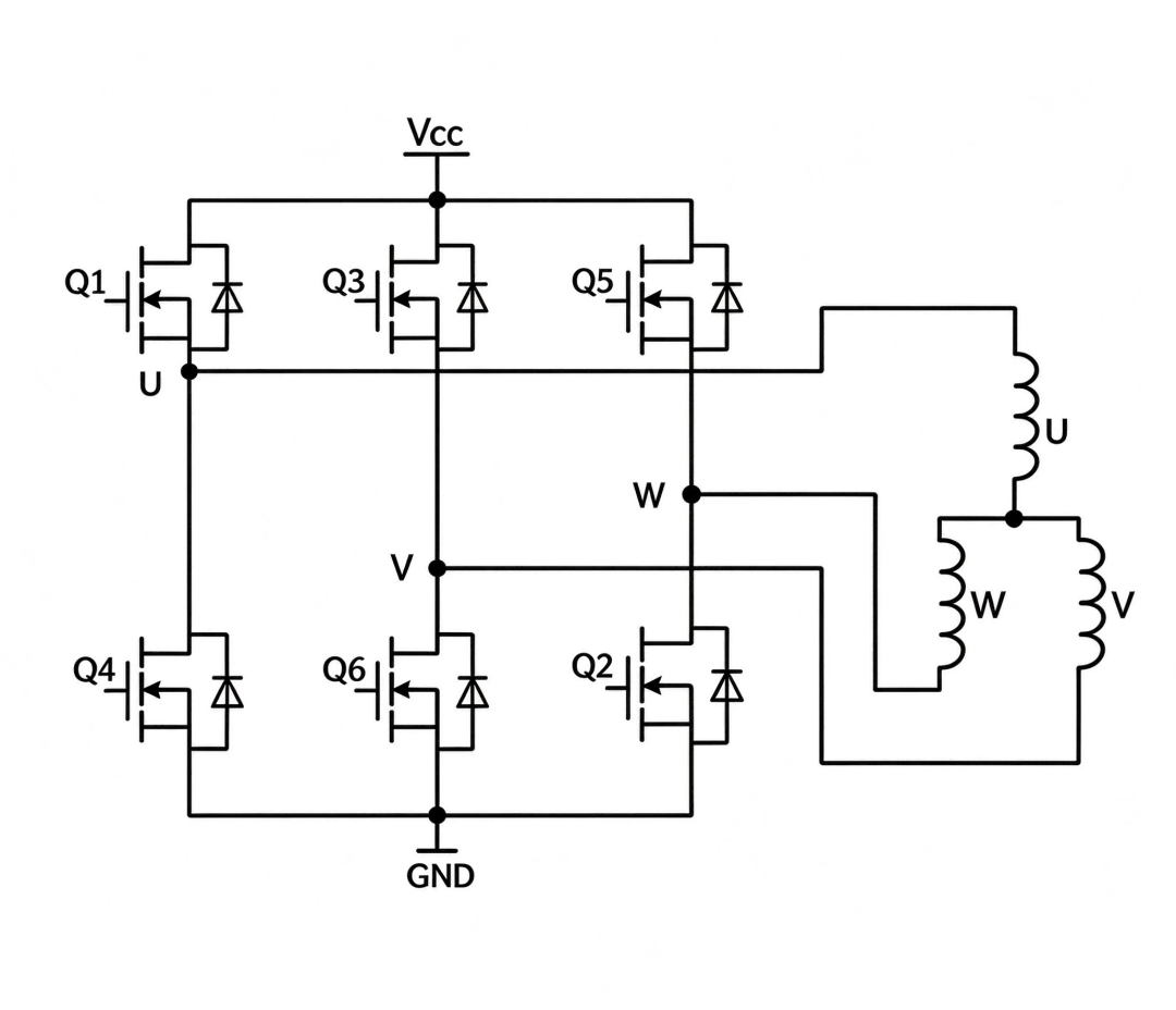
Figure 1: Three-phase full-bridge topology — each joint motor is driven by six SGT MOSFETs, one high-side and one low-side per phase.
Joint motor drive faces three engineering challenges at the same time:
- High frequency, high efficiency: to deliver smooth torque and fast dynamic response, joint drives switch at 20 kHz–50 kHz, so the power devices must keep switching losses low and behave stably at high frequency.
- Space and thermal constraints: the drive sits inside the joint module, where PCB area is extremely limited — and the heat generated by high motor currents has to leave a very small volume.
- Complex dynamic duty: walking, turning, stopping and carrying loads swing the motor current across a wide range; frequent starts, stops and overloads test device reliability.
In this scenario, the strengths of SGT MOSFETs map directly onto the requirements:
- Conduction losses fall directly: under continuous high current, the device heats less, which raises energy efficiency and eases the thermal design of the joint.
- Low Qg and Qgd support high-frequency PWM: switching losses stay under control at 20 kHz–50 kHz and beyond, helping the FOC loop deliver finer torque output and lower current ripple.
- High-density packaging fits the joint: advanced packages such as DFN5×6 — including DFN5×6-DSC dual-side-cooled versions — carry maximum current and provide the best heat path within a minimal PCB footprint, matching the drive's small-form-factor, low-weight goals.
- Qualified for harsh duty: SGT MOSFETs validated through avalanche testing, thermal-resistance testing and aging tests handle the frequent starts, transient overloads and vibration typical of robot operation.
2.2 Li-ion Protection and BMS: The MOSFET in the Main Current Path
Robots usually run on 48V or 60V lithium battery packs that supply every joint motor, controller, sensor and communication module. Lithium cells are energy-dense but sensitive to voltage, current and temperature, so a complete battery management system (BMS) and power protection circuit are mandatory.
The core protection functions — overcharge protection, over-discharge protection, charge and discharge overcurrent protection, short-circuit protection, reverse-polarity protection and pre-charge at power-up — are all executed by power MOSFETs.
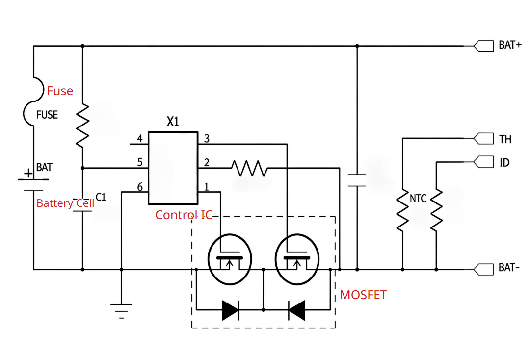
Figure 2: A typical battery protection topology — the SGT MOSFETs sit in series with the battery's main current path and execute every protection action.
Unlike motor drive, battery-protection MOSFETs stay in series with the battery's main current path and continuously carry the machine's entire operating current. RDS(on) therefore becomes the decisive parameter for this role — every milliohm removed means longer runtime and less heat.
In battery protection, the value of SGT MOSFETs concentrates in four points:
- mΩ-class on-resistance: SGT processes achieve RDS(on) as low as 0.55 mΩ (typical value); at tens of amps of continuous current, conduction loss in the battery loop drops to a minimum, directly converting into runtime and reduced thermal pressure.
- High avalanche and short-circuit withstand: abnormal events such as short circuits and voltage spikes require sufficient avalanche energy capability (UIS), so the device survives transient surges before protection triggers — and does not fail in a way that would disable the protection itself.
- Mature voltage platforms with margin: with 48V / 60V battery buses, SGT MOSFETs are available in the 60V, 80V and 100V classes, so designers can balance cost against reliability with a sensible voltage derating margin.
- Low loss, low heat for long-term stability: protection MOSFETs work in the main loop year after year; low loss means a lower temperature rise, which extends device life and the overall reliability of the battery system.
2.3 Joint Drive vs Battery Protection: How Selection Priorities Shift
Joint motor drive and battery protection are both core SGT MOSFET applications, but the two scenarios work differently and call for different priorities. The table below compares the key selection dimensions:
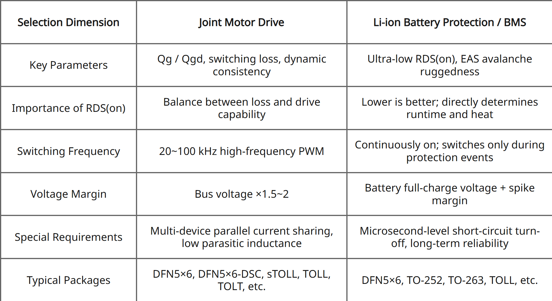
Figure 3: Selection priorities for the two scenarios — Qg/Qgd, switching loss and dynamic consistency for joint drive; ultra-low RDS(on) and avalanche ruggedness for battery protection.
3. How Many SGT MOSFETs Does One Robot Use?
A current mainstream humanoid robot (including dexterous hands) has roughly 40–50 joint motors. Counting the joint-drive function alone, one robot uses about 200–350 SGT MOSFETs; once parallel devices for high-torque joints and the brake-discharge circuits are included, motor-drive-related usage reaches 250–400 pieces per robot. The estimate below breaks the total down by subsystem:
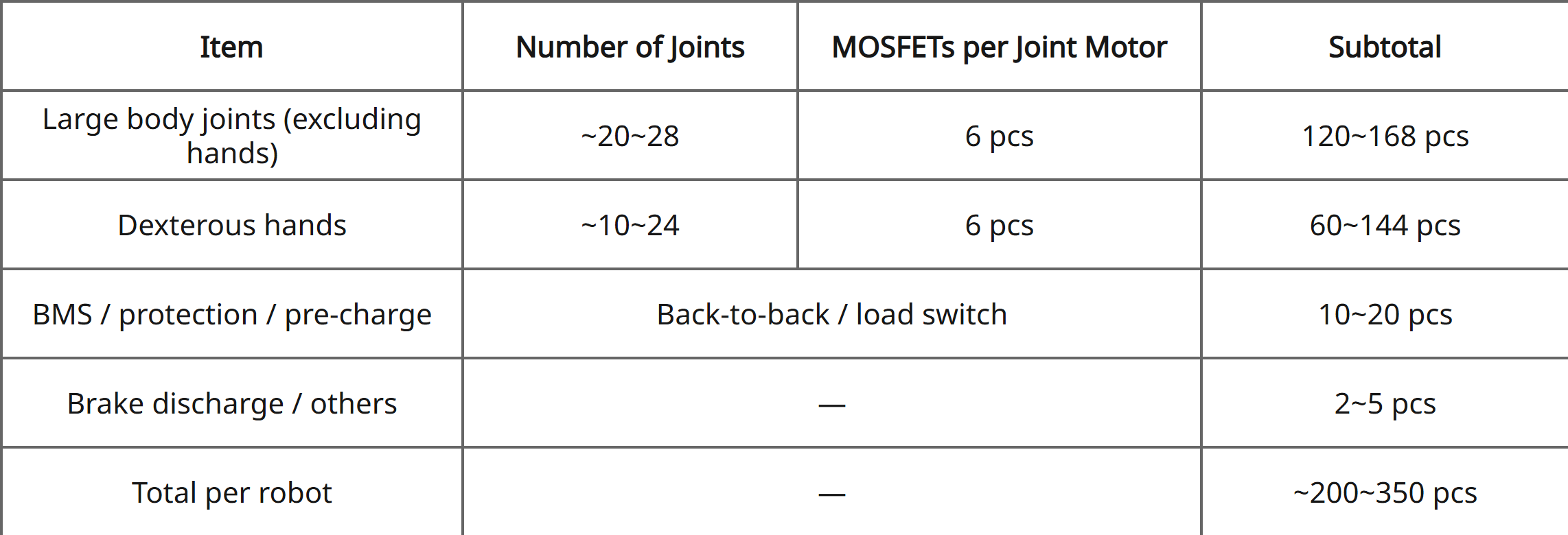
Figure 4: Per-robot SGT MOSFET estimate — joint drives and dexterous hands dominate the count, with BMS protection and brake discharge on top.

4. NCE SGT MOSFET Solutions for Robot Designs
Today's SGT MOSFET voltage platform spans 25V–200V, with mature products at the 40V, 60V, 80V and 100V grades most used in robotics — a complete matrix running from tens of amps to several hundred amps. The range is part of our NCE product range, and the wider power transistor line covers adjacent power stages.
The whole series uses DFN-family packages, and selected current ratings support dual-side cooling — combining ultra-low parasitic inductance with improved heat dissipation. The table below lists the mainstream SGT MOSFETs matched to robot applications:
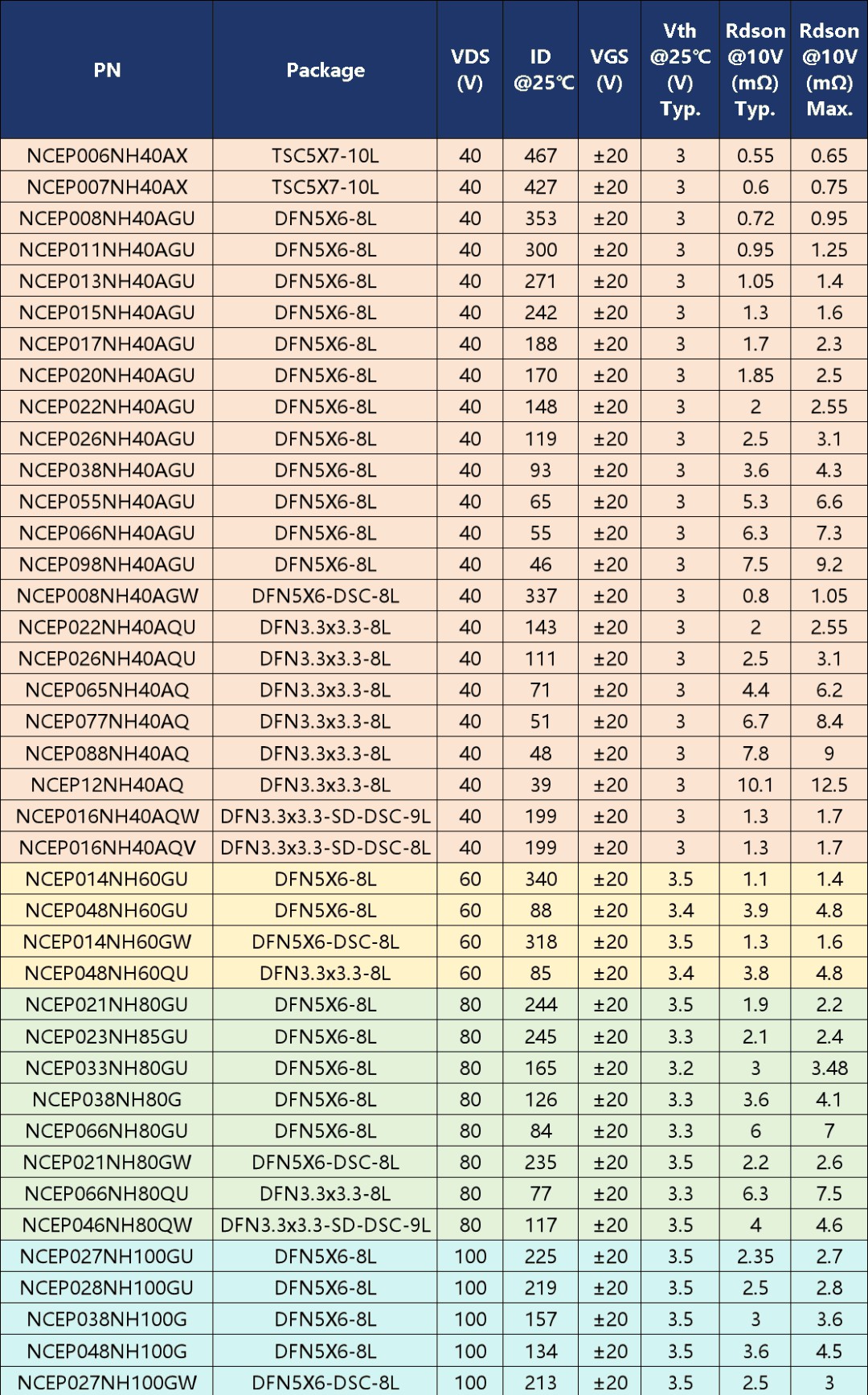
Figure 6: Mainstream SGT MOSFET selection table for robot designs — voltage grades, current ratings, Vth and RDS(on) at a glance.
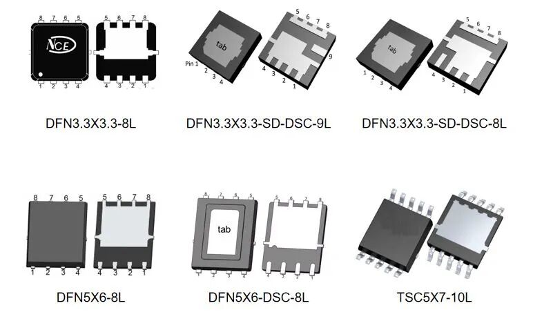
Figure 7: Package families — DFN3.3×3.3, DFN5×6 and TSC5×7 outlines, including DSC dual-side-cooled versions.
For robot platforms, SGT MOSFETs are the rare device family that serves both ends of the powertrain at once: efficient, low-loss drive in every joint, and reliable protection in the battery loop. With a 25V–200V portfolio, DFN packaging and full avalanche, thermal and aging validation, designing both functions around one qualified MOSFET family shortens qualification and simplifies the BOM.
Related pages: browse the MOSFET category, the power transistor range and discrete devices, or see all products.
Designing SGT MOSFETs into a robot platform?
Ask our FAE team for the full SGT MOSFET selection tables, samples and layout guidance — typically within one business day.
Request Sample & DatasheetSGT MOSFET for Robotics: Joint Motor Drive & Battery Protection
Time: 2026-10-22 11:14:20
Humanoid robots are moving out of the laboratory and into mass production, while service and collaborative robots spread through industrial, commercial and home settings. Inside any of these machines, power semiconductors act like muscles and nerves — they set motion performance, energy efficiency and system safety. Among them, the SGT MOSFET (shielded gate trench MOSFET) has become the most widely used core power device in the 48V / 60V / 72V low- and medium-voltage systems of robots, thanks to its combination of low RDS(on), low switching loss and high power density.
1. SGT MOSFET: A Preferred Choice for Low- and Medium-Voltage Power Devices
SGT (Shielded Gate Trench) MOSFETs introduce a shielded electrode below the gate of a conventional trench MOSFET. That structure brings gate–drain capacitance (Cgd) and on-resistance (RDS(on)) down at the same time, while also improving the device's voltage capability.
Compared with conventional power MOSFETs, SGT MOSFETs offer four core advantages:
- Lower on-resistance: on the same die area, RDS(on) can drop by 30%–50%, which cuts conduction losses and raises system efficiency.
- Faster switching: gate charge Qg and gate–drain charge Qgd fall significantly, keeping switching losses low — an ideal match for high-frequency PWM control.
- Higher power density: small packages can carry large currents, fitting the tight space of robot joints and battery compartments.
- Wide voltage coverage: the mature 20V–150V platform covers the 48V / 60V / 72V bus levels commonly used in robots.
Together, these characteristics make SGT MOSFETs an ideal choice for the low- and medium-voltage power systems of robots.
2. Two Core Application Scenarios in Humanoid Robots
2.1 Joint Motor Drive: Six MOSFETs per Motor
A humanoid robot carries dozens of high-dynamic joints, and every joint needs its own high-performance motor drive. Joints are typically actuated by brushless DC motors (BLDC) or permanent-magnet synchronous motors (PMSM), and each motor is driven by a three-phase full-bridge inverter — one SGT MOSFET in each high-side and low-side position, six devices per motor. The topology looks like this:
Figure 1: Three-phase full-bridge topology — each joint motor is driven by six SGT MOSFETs, one high-side and one low-side per phase.
Joint motor drive faces three engineering challenges at the same time:
- High frequency, high efficiency: to deliver smooth torque and fast dynamic response, joint drives switch at 20 kHz–50 kHz, so the power devices must keep switching losses low and behave stably at high frequency.
- Space and thermal constraints: the drive sits inside the joint module, where PCB area is extremely limited — and the heat generated by high motor currents has to leave a very small volume.
- Complex dynamic duty: walking, turning, stopping and carrying loads swing the motor current across a wide range; frequent starts, stops and overloads test device reliability.
In this scenario, the strengths of SGT MOSFETs map directly onto the requirements:
- Conduction losses fall directly: under continuous high current, the device heats less, which raises energy efficiency and eases the thermal design of the joint.
- Low Qg and Qgd support high-frequency PWM: switching losses stay under control at 20 kHz–50 kHz and beyond, helping the FOC loop deliver finer torque output and lower current ripple.
- High-density packaging fits the joint: advanced packages such as DFN5×6 — including DFN5×6-DSC dual-side-cooled versions — carry maximum current and provide the best heat path within a minimal PCB footprint, matching the drive's small-form-factor, low-weight goals.
- Qualified for harsh duty: SGT MOSFETs validated through avalanche testing, thermal-resistance testing and aging tests handle the frequent starts, transient overloads and vibration typical of robot operation.
2.2 Li-ion Protection and BMS: The MOSFET in the Main Current Path
Robots usually run on 48V or 60V lithium battery packs that supply every joint motor, controller, sensor and communication module. Lithium cells are energy-dense but sensitive to voltage, current and temperature, so a complete battery management system (BMS) and power protection circuit are mandatory.
The core protection functions — overcharge protection, over-discharge protection, charge and discharge overcurrent protection, short-circuit protection, reverse-polarity protection and pre-charge at power-up — are all executed by power MOSFETs.
Figure 2: A typical battery protection topology — the SGT MOSFETs sit in series with the battery's main current path and execute every protection action.
Unlike motor drive, battery-protection MOSFETs stay in series with the battery's main current path and continuously carry the machine's entire operating current. RDS(on) therefore becomes the decisive parameter for this role — every milliohm removed means longer runtime and less heat.
In battery protection, the value of SGT MOSFETs concentrates in four points:
- mΩ-class on-resistance: SGT processes achieve RDS(on) as low as 0.55 mΩ (typical value); at tens of amps of continuous current, conduction loss in the battery loop drops to a minimum, directly converting into runtime and reduced thermal pressure.
- High avalanche and short-circuit withstand: abnormal events such as short circuits and voltage spikes require sufficient avalanche energy capability (UIS), so the device survives transient surges before protection triggers — and does not fail in a way that would disable the protection itself.
- Mature voltage platforms with margin: with 48V / 60V battery buses, SGT MOSFETs are available in the 60V, 80V and 100V classes, so designers can balance cost against reliability with a sensible voltage derating margin.
- Low loss, low heat for long-term stability: protection MOSFETs work in the main loop year after year; low loss means a lower temperature rise, which extends device life and the overall reliability of the battery system.
2.3 Joint Drive vs Battery Protection: How Selection Priorities Shift
Joint motor drive and battery protection are both core SGT MOSFET applications, but the two scenarios work differently and call for different priorities. The table below compares the key selection dimensions:
Figure 3: Selection priorities for the two scenarios — Qg/Qgd, switching loss and dynamic consistency for joint drive; ultra-low RDS(on) and avalanche ruggedness for battery protection.
3. How Many SGT MOSFETs Does One Robot Use?
A current mainstream humanoid robot (including dexterous hands) has roughly 40–50 joint motors. Counting the joint-drive function alone, one robot uses about 200–350 SGT MOSFETs; once parallel devices for high-torque joints and the brake-discharge circuits are included, motor-drive-related usage reaches 250–400 pieces per robot. The estimate below breaks the total down by subsystem:
Figure 4: Per-robot SGT MOSFET estimate — joint drives and dexterous hands dominate the count, with BMS protection and brake discharge on top.
4. NCE SGT MOSFET Solutions for Robot Designs
Today's SGT MOSFET voltage platform spans 25V–200V, with mature products at the 40V, 60V, 80V and 100V grades most used in robotics — a complete matrix running from tens of amps to several hundred amps. The range is part of our NCE product range, and the wider power transistor line covers adjacent power stages.
The whole series uses DFN-family packages, and selected current ratings support dual-side cooling — combining ultra-low parasitic inductance with improved heat dissipation. The table below lists the mainstream SGT MOSFETs matched to robot applications:
Figure 6: Mainstream SGT MOSFET selection table for robot designs — voltage grades, current ratings, Vth and RDS(on) at a glance.
Figure 7: Package families — DFN3.3×3.3, DFN5×6 and TSC5×7 outlines, including DSC dual-side-cooled versions.
For robot platforms, SGT MOSFETs are the rare device family that serves both ends of the powertrain at once: efficient, low-loss drive in every joint, and reliable protection in the battery loop. With a 25V–200V portfolio, DFN packaging and full avalanche, thermal and aging validation, designing both functions around one qualified MOSFET family shortens qualification and simplifies the BOM.
Related pages: browse the MOSFET category, the power transistor range and discrete devices, or see all products.
Designing SGT MOSFETs into a robot platform?
Ask our FAE team for the full SGT MOSFET selection tables, samples and layout guidance — typically within one business day.
Request Sample & DatasheetOther Articles
-

SGT MOSFET for Robotics: Joint Motor Drive & Battery Protection
-
YQ8563: Drop-In Low-Power RTC Replacement for NXP PCF8563
-
Industrial Robot Clocking: Why MEMS Timing Beats Quartz
-
YQ8025T RTC: Built-in DTCXO, No Crystal — RX8025T Alternative
-
Sunlord WL-FS Wire-Wound Ferrite Inductors for Audio Lines: Purer Sound, Lower THD
-
Epson TSX-3225C Crystal: Pin-to-Pin FA-238 Upgrade for 5G, IoT & Automotive
-
NCE90N800F 900V Super-Junction MOSFET — CoolMOS Alternative
-
SiTime PNT Timing Foundation: Why Precision Oscillators Define Modern Navigation
-
NCE Gen.8 IGBT Series: 1200V/140A NCE140GD120VTP4 Benchmarks Ahead of Top Competitors
-
YXC High-Performance Timing Devices Empowering a New Experience in AI Wearables


Copyright By © YQM ELECTRONICS INTL LIMITED SITEMAP
Email: sales@yqmec.com

点击右上角
分享给朋友吧


